
Apparatus for and a method of machining two portions

Inactive Publication Date: 2002-01-01
TOYODA MASCH WORKS LTD
View PDF7 Cites 13 Cited by
  • Summary
  • Abstract
  • Description
  • Claims
  • Application Information

AI Technical Summary

Benefits of technology

Accordingly, an object of the present invention is to solve the above mentioned problems and is to provide a machining method for grinding pin portions of a crankshaft in which a deterioration is prevented in a machining accuracy of the pin portions by restraining a load fluctuation acting on a main spindle rotating the crankshaft.
Briefly, according to the present invention, two pin portions of one rotating crankshaft having different rotational phase are respectively ground by respective two grinding wheels which are controllably moved synchronously with a rotation of the crankshaft in accordance with pin portion data. In the pin portion data, the two pin portions to be ground simultaneously are memorized as a combination. The two pin portions are different from each other in rotational phase, so that directions of grinding resistance acting on the respective pin portions are also different from each other, Therefore, a load fluctuation acting on a main spindle can be reduced compared with either case that only one pin portion is ground or case that two pin portions having the same rotational phase are simultaneously ground.
Further, a rotational phase difference between the two pin portions in the combination is set as 180.degree.. In a case that the grinding wheels on the wheel heads rotate in the same condition, the grinding resistances act on the two pin portions by the same amount in positive and negative directions. Accordingly, the grinding resistances can be almost canceled in each other, so that loads acting on the main spindle by the grinding resistances can be almost canceled also, whereby load fluctuation acting thereon can be reduced. Therefore, grinding accuracy (i.e., roundness) on the two pin portions can be improved. Even if a rotational phase difference between the two pin portions in the combination is set as 60.degree. or 120.degree., the grinding resistances can be reduced in each other, so that loads acting on the main spindle by the grinding resistances can be also reduced.
The load fluctuation acting on the main spindle can be reduced, so that the grinding accuracy (i.e., roundness) on the two pin portions can be improved compared with either case that only one pin portion is ground or case that two pin portions having the same rotational phase are simultaneously ground. The combination of the two pin portions to be simultaneously ground can be freely changed in a condition that the rotational phase difference is set as 60.degree. or 120.degree.. Even if the adjacent two pin portions cannot be simultaneously ground due to the machine construction, the grinding accuracy (i.e., roundness) on the two pin portions can be improved by changing the combination of the two pin portions.

Problems solved by technology

Therefore, there is such a demerit that a grinding accuracy is deteriorated by a load fluctuation acting on the main spindle.

Method used


Image

  • Apparatus for and a method of machining two portions
  • Apparatus for and a method of machining two portions
  • Apparatus for and a method of machining two portions

Examples


Embodiment Construction

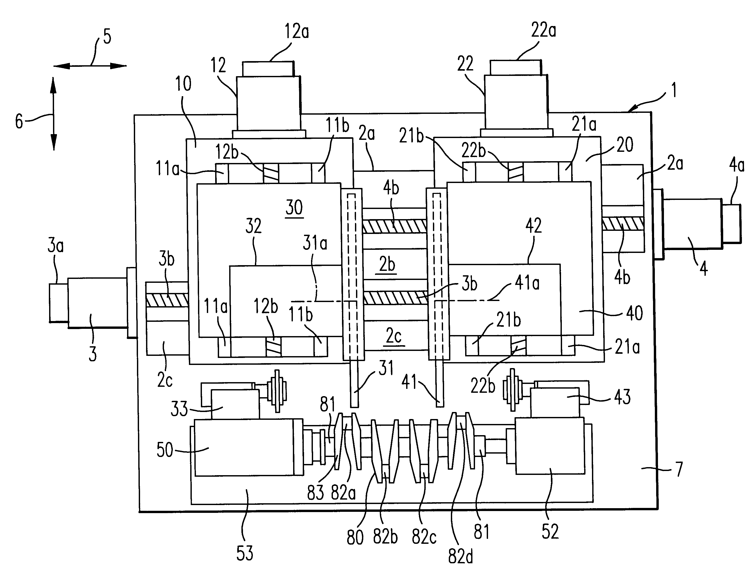
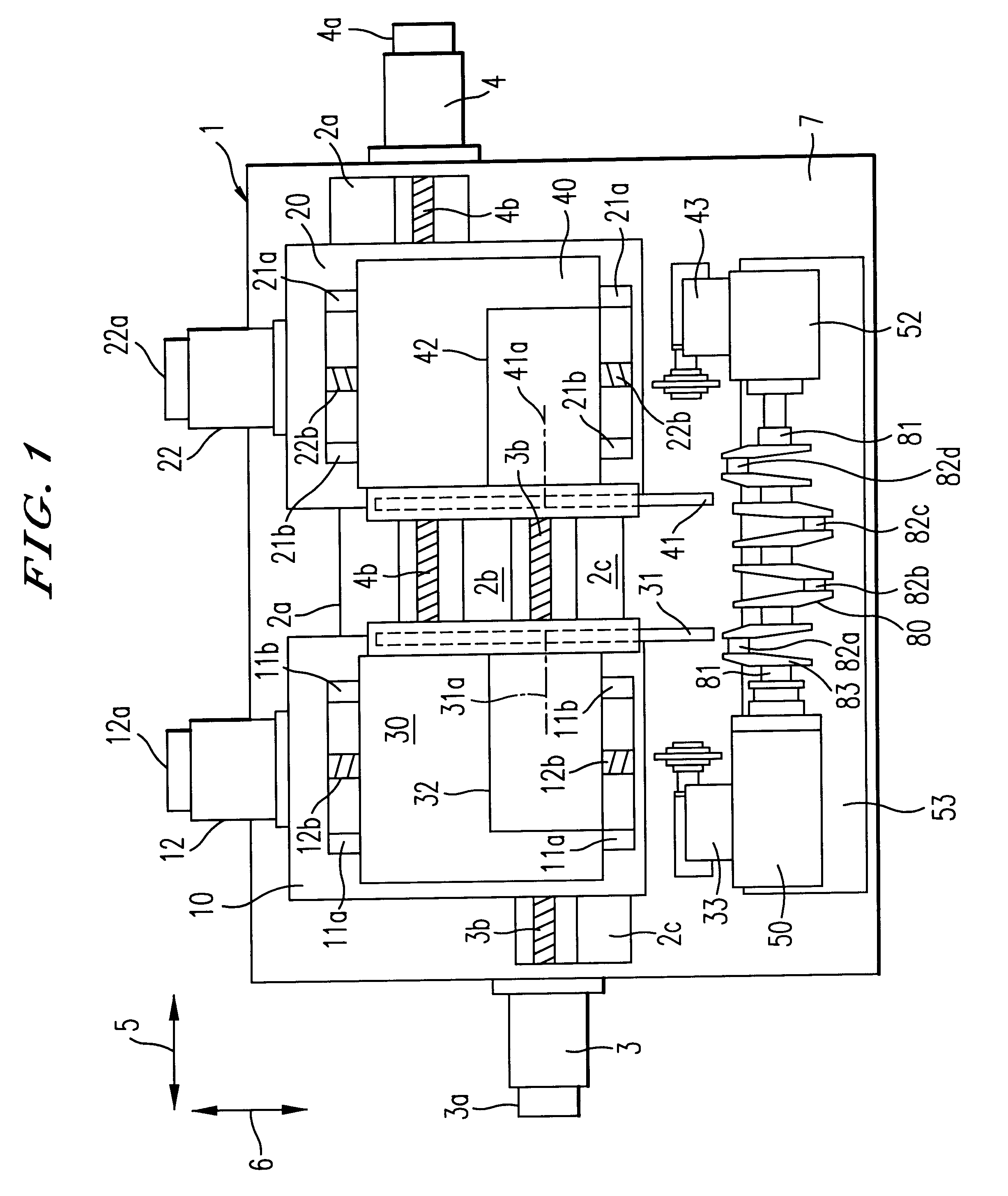
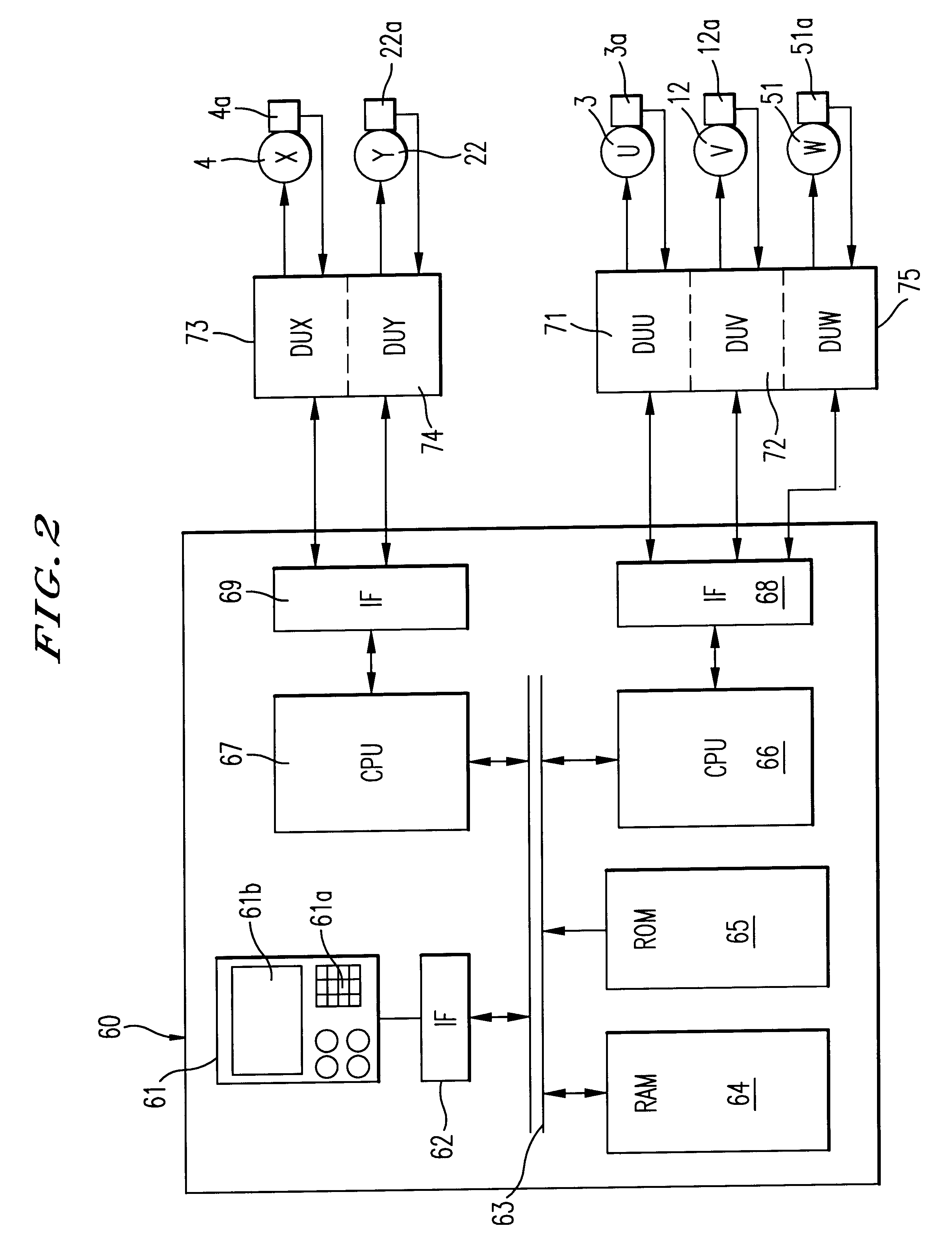
An embodiment according to the present invention will be described hereinafter with reference to the drawings. FIG. 1 shows a top plane view of a grinding machine according to the present invention, and FIG. 2 shows a block diagram of a numerical control unit according thereto.

In FIGS. 1 and 2, Z-axis guide rails 2a, 2b and 2c are secured to a base 7 of a grinding machine 1. Further, a left-side table motor 3 is fixed on the base 7, to which a ball screw is rotatably connected. On the other hand, a right-side table motor 4 is fixed on the base 7, to which a ball screw 4a is rotatably connected. An encoder 3a is attached to the left-side table motor 3 to detect a rotational position thereof, while an encoder 4a is attached to the right-side table motor 4 to detect a rotational position thereof A left-side table 10 and a right-side table 20 are slidably arranged along the axis Z-rails 2a, 2b and 2c in a Z-axis direction (direction indicated by an arrow 5). On the left-side table 10, t...


PUM

PropertyMeasurementUnit
Angleaaaaaaaaaa
Angleaaaaaaaaaa
Phaseaaaaaaaaaa

Abstract

A grinding machine includes a spindle head for rotatably driving a crankshaft around a journal center as a rotational axis and, two wheel heads that support respective two grinding wheels and that advance and retract in a direction perpendicular to the rotational axis independently with each other. Two of plural pin portions of the rotating crankshaft are simultaneously ground by the respective two grinding wheels, in which rotational phases of the two pin portions are different from each other. Further, the rotational phases of the two pin portions are stored as a combination in a memory. The two pin portions are simultaneously ground in accordance with the combination by the respective two grinding wheels.

Description

BACKGROUND OF THE INVENTION1. Field of the InventionThe present invention relates to an apparatus for and a method of grinding a crankshaft, more particularly, to an apparatus for and a method of preventing a machining accuracy from deteriorating by restraining a load fluctuation acting on a main spindle when grinding pin portions of a crankshaft.2. Description of the Related ArtSince a pin portion of a crankshaft used in an engine is rotatably connected to a connecting rod, it is required to accurately machine the pin portion in its radial dimension and roundness.As disclosed in Japanese Patent Publication (Kokai) No. S54(1979)-71495, it is known such a grinding machine that grinds a pin portion of one crankshaft eccentrically moving around a journal portion as a rotational center, in which two wheel heads are independently advanced and retracted synchronously with a rotation of a main spindle.In such a conventional grinding machine, the pin portion revolves around the rotational c...

Claims


Application Information

Patent Timeline
IPC IPC(8): B24B27/00B24B49/00B24B5/42B24B5/00B23B5/18B23C3/06
CPCB24B5/42B24B49/00B24B27/0076
Inventor SANO, SHOICHIIDO, MASAHIROYAMAGUCHI, SATOSHI
Owner TOYODA MASCH WORKS LTD
Learn More