Rear body structure for vehicle

a rear body and vehicle technology, applied in the direction of roofs, dismountable/non-dismountable seats, pedestrian/occupant safety arrangements, etc., can solve the problems of unavoidable restraint, unavoidable preventing the rear body section from crushing and thrusting, and not always desirabl

Inactive Publication Date: 2002-01-15
MAZDA MOTOR CORP
View PDF21 Cites 14 Cited by
  • Summary
  • Abstract
  • Description
  • Claims
  • Application Information

AI Technical Summary

Problems solved by technology

For instance, a vehicle having three rows of seats arranged in a lengthwise direction from the front to the back of the vehicle or a vehicle having a short overall body length even though it has only two rows of seats are unavoidably restrained from providing a long distance or a large space between the rear seats and the rear wall of the vehicle body.
In such a vehicle which has only a short distance or a small space between the rear wall of the vehicle body and the rear row of seats, it is unavoidable to prevent the rear body section from crushing and thrusting at the back seats in an event of a collision from the back.
While it is possible to provide the safety of passengers, in particular, seating on the rear seats by significantly increased strength of the rear body portion, it is not always desirable because it is accompanied by an increased w eight of th e rear body section.
Further, it is unnecessary to locate the rear seats as backward as possible in order to prevent the spare tire from rising up.

Method used


Image

  • Rear body structure for vehicle
  • Rear body structure for vehicle
  • Rear body structure for vehicle

Examples


Embodiment Construction

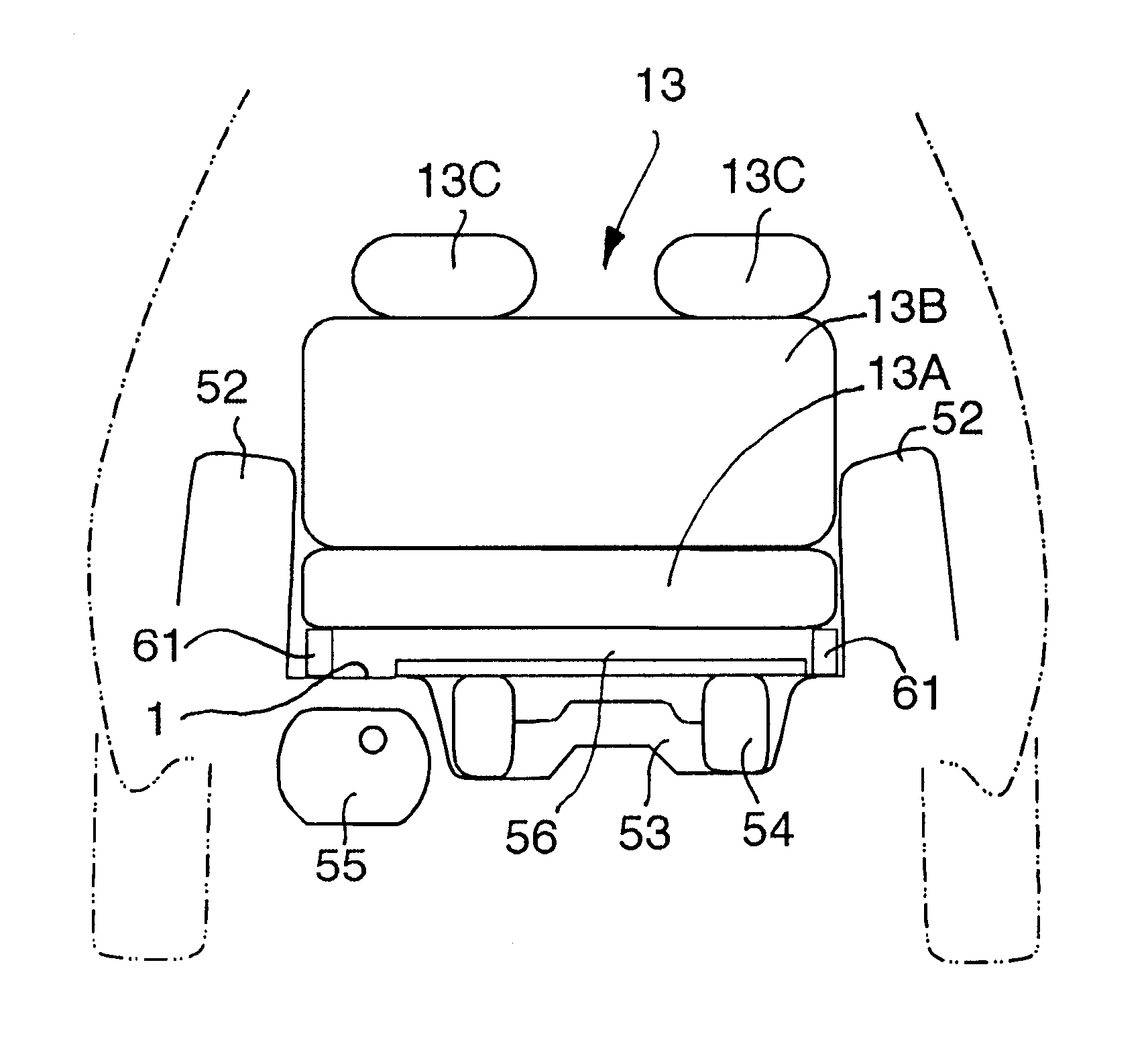
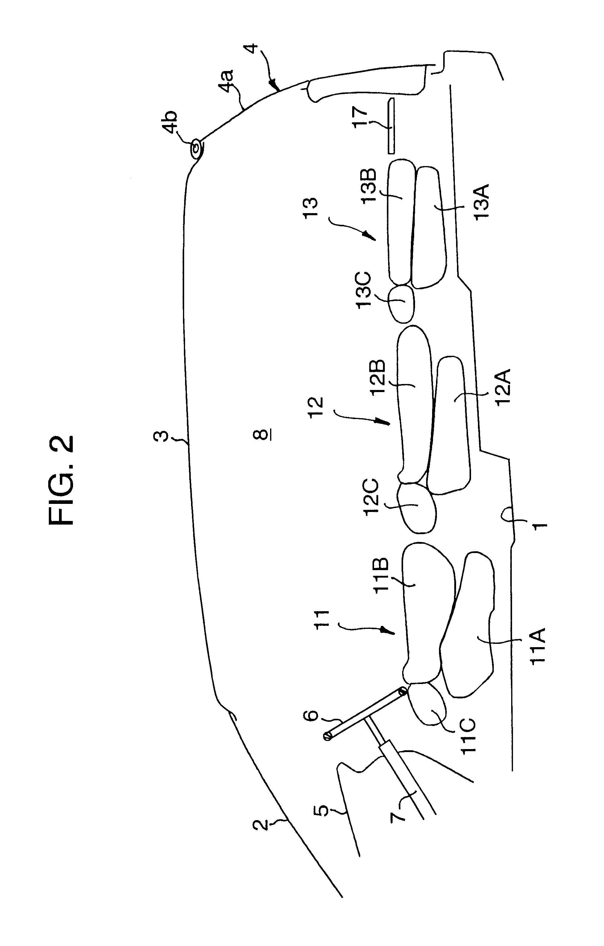
Referring to the drawings in detail and, in particular, to FIG. 1, a vehicle has a floor panel 1, a front windshield 2, a roof panel 3, a back door 4 and an instrument panel 5. The back door 4 has a rear windshield 4a and is pivotally mounted on a shaft 4b so as to turn between an open position and a closed position. The vehicle further has a steering wheel 6 mounted on a tip end of a steering shaft 7. A steering arrangement incorporates a tilt mechanism and a telescopic mechanism. The steering wheel 6 is adjustable in height and position by being swiveled up and down or back and forth.

A passenger compartment 8 is defined by and between the instrument panel 5 and the back door 4. In the passenger compartment there are installed three rows of seats arranged in the lengthwise direction of the vehicle, namely a first or front row of seats 11, a second or middle row of seat 12, and a third or rear row of seats 13. Each row of seats are disposed side by side in the transverse direction. ...


PUM


Abstract

Disclosed herein is a vehicle rear body structure to reduce the amount of the transformation of the vehicle rear body portion for the back row seat in the event of the rear end collision. A pair of the rear wheel houses (51) are formed at the back part of a floor panel. A suspension tower (52) is formed to the rear wheel house (51). The pan (53) is formed nearly in the center part in the traverse direction of the floor panel 1 behind the suspension tower (52). The pan (53) is formed like the plate so as to being opened upward. The bottom of the pan (53) is substantially horizontal. The spare tire (54) is kept substantially horizontal in the pan (53).

Description

1. Field of the InventionThe present invention is directed to a rear body structure for a vehicle.2. Description of Related ArtA spare tire is often loaded on a rear section of a vehicle body. Japanese Utility Model Publication No.6-11906 has disclosed a storage pan for storing a spare tire. The storage pan is formed as the rear part of a floor panel and inclines to the front so as to carry a spare tire inclined forward up thereon. Because of the inclined position, the spare tire allows a rear body section of the vehicle to be appropriately crushed without thrusting the rear body section in an event where the vehicle is collided from the back.Some types of vehicles are provided with rear seats with a small space to a rear wall of the vehicle body. For instance, a vehicle having three rows of seats arranged in a lengthwise direction from the front to the back of the vehicle or a vehicle having a short overall body length even though it has only two rows of seats are unavoidably restr...

Claims


Application Information

Patent Timeline
Patent Type & Authority Patents(United States)
IPC IPC(8): B60N2/30B62D43/00B62D43/10B62D25/20B60R21/02
CPCB60N2/3011B62D43/10B60N2/3093B60N2/305
Inventor TOYOTA, MINORUKIMURA, YASUYUKINAKAO, KOJI
Owner MAZDA MOTOR CORP
Why Eureka
Try Eureka