DRAM cell buried strap leakage measurement structure and method

a leakage measurement and buried strap technology, applied in semiconductor/solid-state device testing/measurement, instruments, transistors, etc., can solve the problems of reducing stored charge, reducing charge, and reducing the dram's sensitivity to noise, so as to reduce the dram's leakage rate, and the leakage rate is high

Inactive Publication Date: 2002-01-15
IBM CORP
View PDF5 Cites 45 Cited by
  • Summary
  • Abstract
  • Description
  • Claims
  • Application Information

AI Technical Summary

Problems solved by technology

Unfortunately, shrinking the capacitor area reduces capacitance and, consequently, reduces stored charge.
Reduced charge means what is stored in the DRAM is more susceptible to noise, soft errors, leakage and other typical DRAM problems.
However, even though the storable charge may be maintained, cell le

Method used


Image

  • DRAM cell buried strap leakage measurement structure and method
  • DRAM cell buried strap leakage measurement structure and method
  • DRAM cell buried strap leakage measurement structure and method

Examples


Embodiment Construction

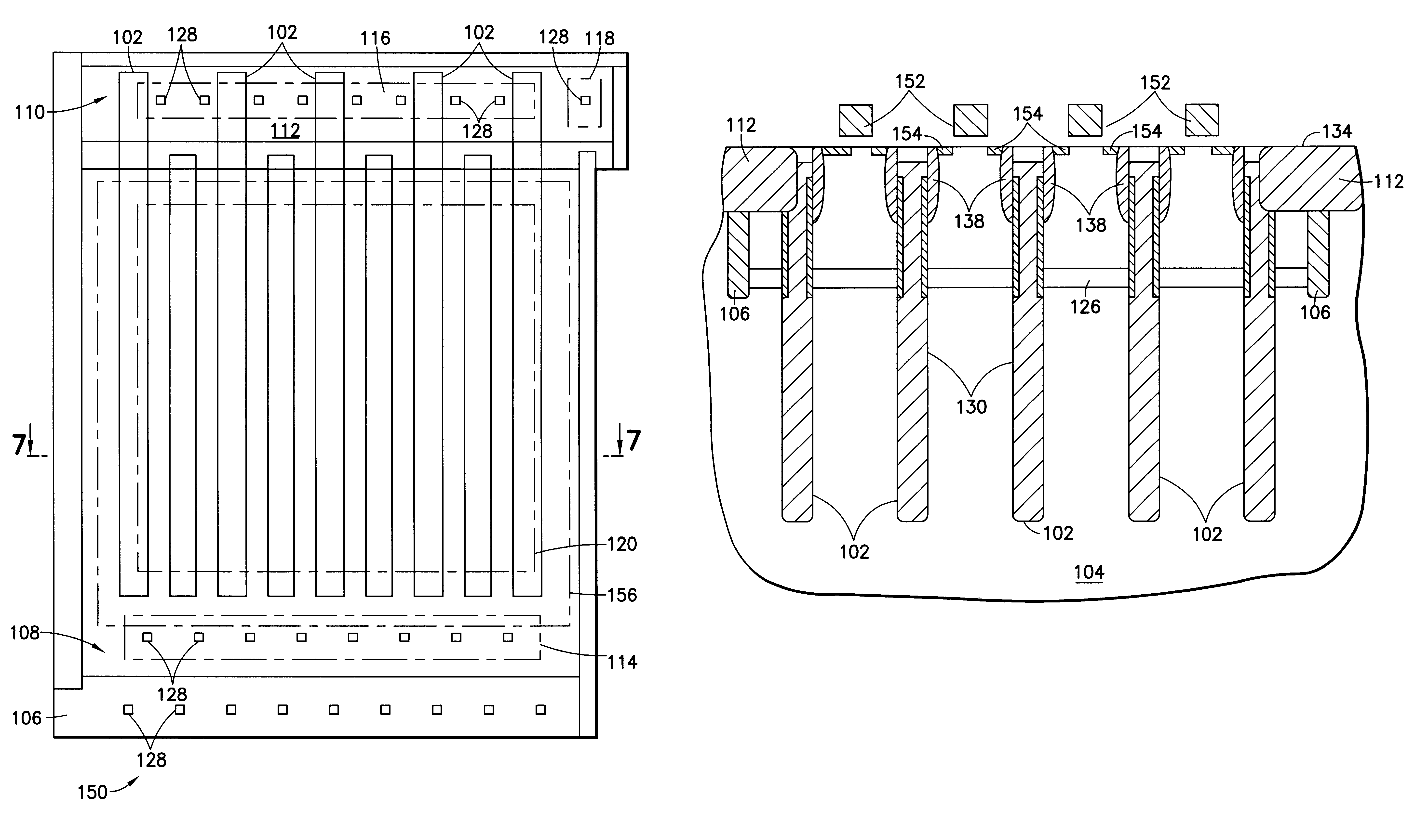
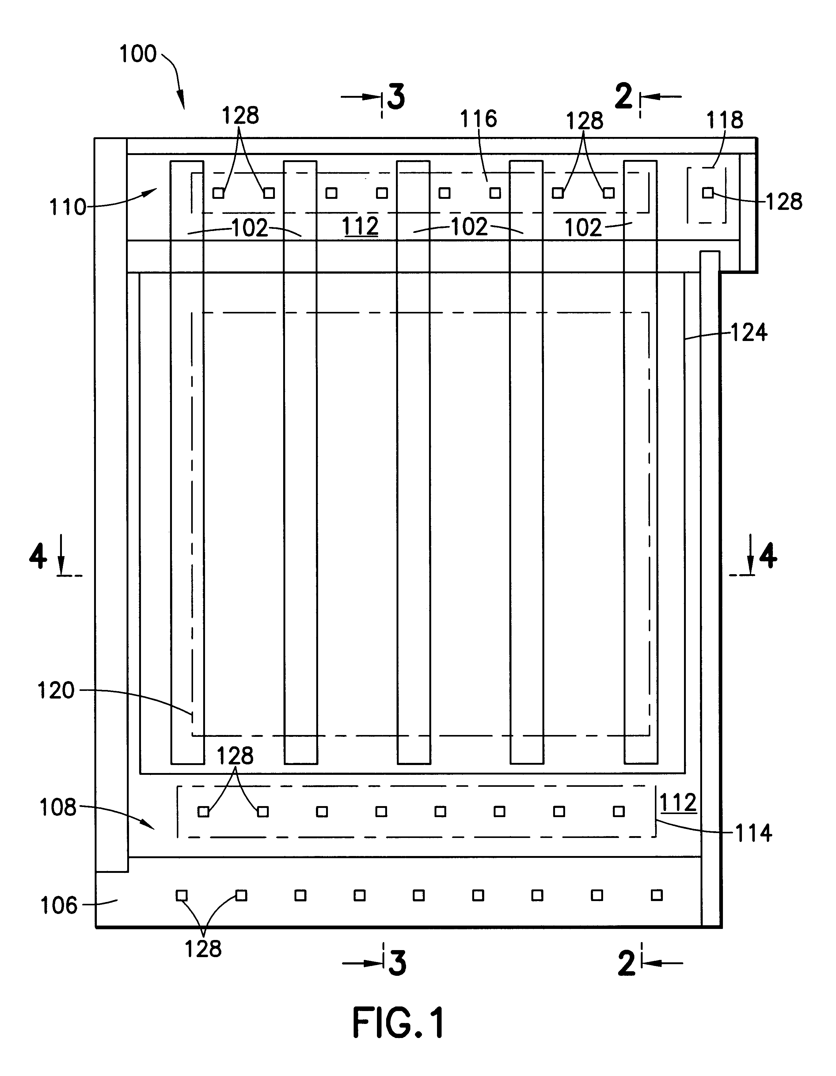
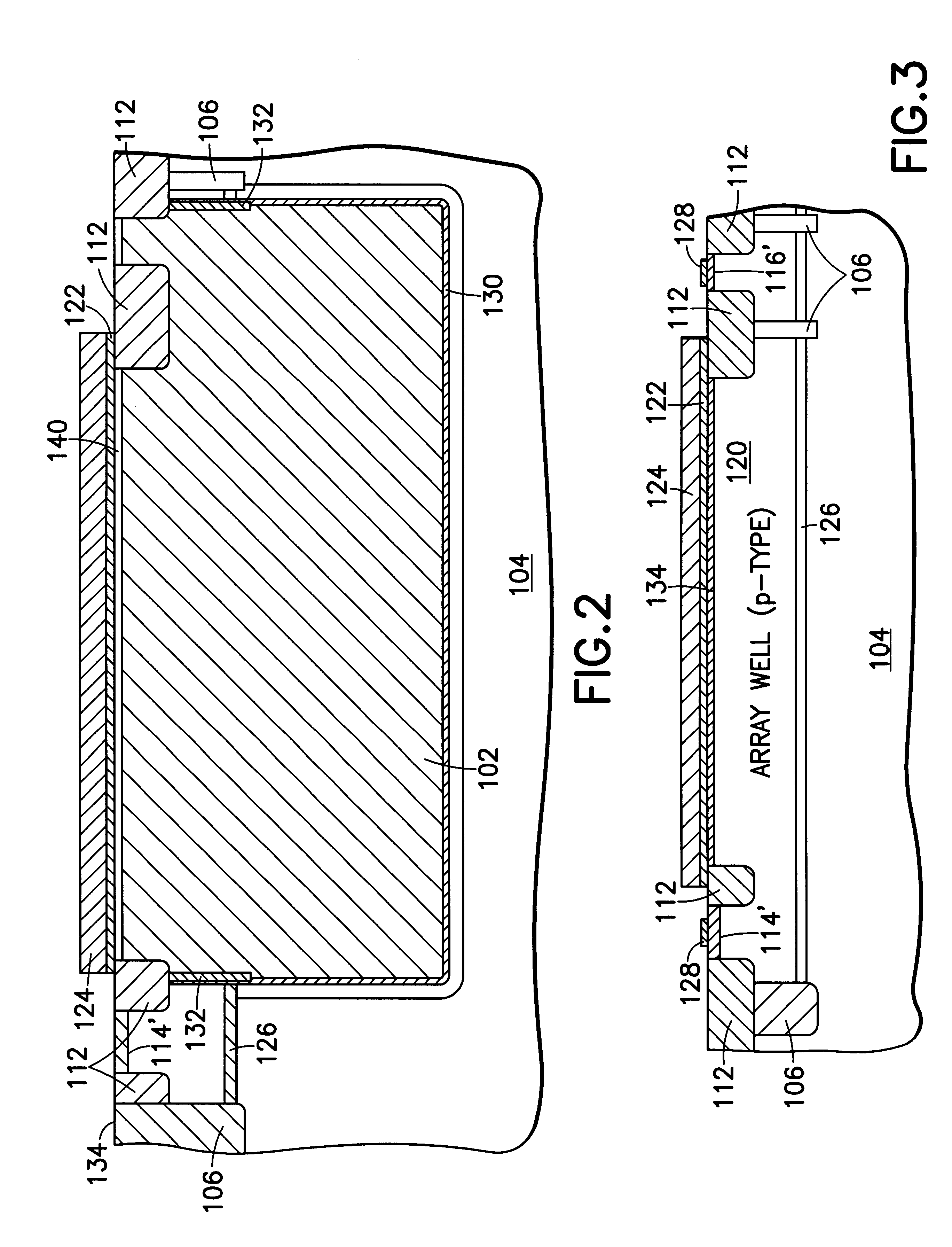
Referring now to the drawings, and more particularly, FIG. 1 shows a plan view of a first buried strap test structure 100 of the preferred embodiment cell leakage test structure of the present invention. The preferred embodiment cell leakage test structure includes two (2) buried strap test structures, an isolated buried strap test structure 100 of FIG. 1 and, a second structure wherein the buried straps are connected to source diffusions as described hereinbelow. Thus, the first test structure 100 includes a large isolated strap junction area for isolating and determining strap diffusion leakage. FIG. 2 is a cross-section of the first test structure 100 of FIG. 1 through 2--2. FIG. 3 is a cross-section of the first test structure 100 of FIG. 1 through 3--3. FIG. 4 is a cross-section of the first test structure 100 of FIG. 1 through 4--4.

It should be noted that the strap is described herein as n-type for example only and not as a limitation. The present invention may be used advanta...


PUM


Abstract

A test structure and method for determining DRAM cell leakage. The cell leakage test structure includes a pair of buried strap test structures. Each buried strap test structure includes multiple trench capacitors formed in a silicon body. Each trench capacitor is connected to a trench sidewall diffusion by at least one buried strap. An n-well ring surrounds each buried strap test structure and divides the buried strap test structure into two separate array p-wells, one being a contact area and the other a leakage test area. The contact area includes contacts to the trench capacitor plates for the corresponding buried strap test structure. In one buried strap test structure, a layer of polysilicon, essentially covers the trench capacitors in the leakage test area to block source/drain region formation there. The other of the two buried strap test structures includes polysilicon lines simulating wordlines with source and drain regions form on either side. A buried n-band contacts the n-well rings, essentially forming an isolation tub around each array well. Cell leakage is measured by measuring leakage current in each buried strap test structure, individually, and then extracting individual leakage components from the measured result.

Description

1. Field of the InventionThe present invention generally relates to semiconductor memories and, more particularly, to a test structure for determining leakage in dynamic random access memory cells.2. Background DescriptionDynamic Random Access Memory (DRAM) cells are well known. A DRAM cell is essentially a capacitor for storing charge coupled to a pass transistor (also called a pass gate or access transistor) for transferring charge to and from the capacitor. The absence or presence of charge on the capacitor corresponds to a logic value of data stored in the cell. Because cell size determines chip density, size and cost, reducing cell area is one of the DRAM designer's primary goals.Reducing cell area is done, normally, by shrinking feature sizes to shrink the cell. In addition to shrinking the cell features, the most effective way to reduce cell area is to reduce the largest feature in the cell, typically, the area of the storage capacitor. Unfortunately, shrinking the capacitor ...

Claims


Application Information

Patent Timeline
IPC IPC(8): G11C29/04G11C29/50H01L21/70H01L21/8242
CPCH01L27/10867G11C29/50H01L22/34H10B12/0385
Inventor IYER, SUNDAR K.CHAKRAVARTI, SATYAIYER, SUBRAMANIAN S.
Owner IBM CORP
Why Eureka
Try Eureka