Liquid crystal display device

a liquid crystal display and active matrix technology, applied in the direction of electrographic process apparatus, instruments, polarising elements, etc., can solve the problems of narrow viewing angle at which a satisfactory image can be observed, affecting the quality of display contrast, and reducing the aperture ratio

Inactive Publication Date: 2002-01-15
SHIN KOH DEN TECH LTD +1
View PDF3 Cites 63 Cited by
  • Summary
  • Abstract
  • Description
  • Claims
  • Application Information

AI Technical Summary

Benefits of technology

is to provide a vertical alignment mode liquid crystal display device which is capable of perfectly achieving a contrast compensation

Problems solved by technology

Therefore, there has been a problem that a perfectly black displaying can not be acquired when the display device is viewed obliquely, quality contrast of the display is lowered, and viewing angles at which a satisfactory image can be observed is narrow.
However, in the IPS mode liquid crystal display device, since a comb-shaped opaque electrode is, for example, provided on one of the substrates existing on both sides of the liquid crystal layer, this liquid crystal display device involves a problem that an aperture ratio decreases.
The IPS mode liquid crystal display device having a low aperture ratio is disadvantageous for portable equipment such as a notebook type personal computer in which low power consumption is required, and so it is generally used at present as a standalone monitor equipment.
In the vertical alignment mode liquid crystal display device, although a contrast when viewed from the front is extremely good, a contrast when viewed from up

Method used


Image

  • Liquid crystal display device
  • Liquid crystal display device
  • Liquid crystal display device

Examples


Embodiment Construction

The embodiments of the present invention will be described below with reference to the accompanying drawings.

There exists different types of liquid crystal display devices. A bright display in which a light transmits through a liquid crystal layer at its maximum is easier to realize than a dark display in which the light is shielded by the liquid crystal layer at its maximum. That is, a white displaying state is realized more easily than a black displaying state. Therefore, in order to enhance the displaying contrast, it is exceedingly essential to increase a density of the black display. In each style of the liquid crystal displaying, a variety of considerations on how to achieve an excellent black display have been made. In the liquid crystal display device of the twisted nematic mode which has been heretofore used, the liquid crystal molecules are in a rotated state or in a vertical alignment state depending on supplying of a current. The black display in the homogeneous vertical...


PUM


Abstract

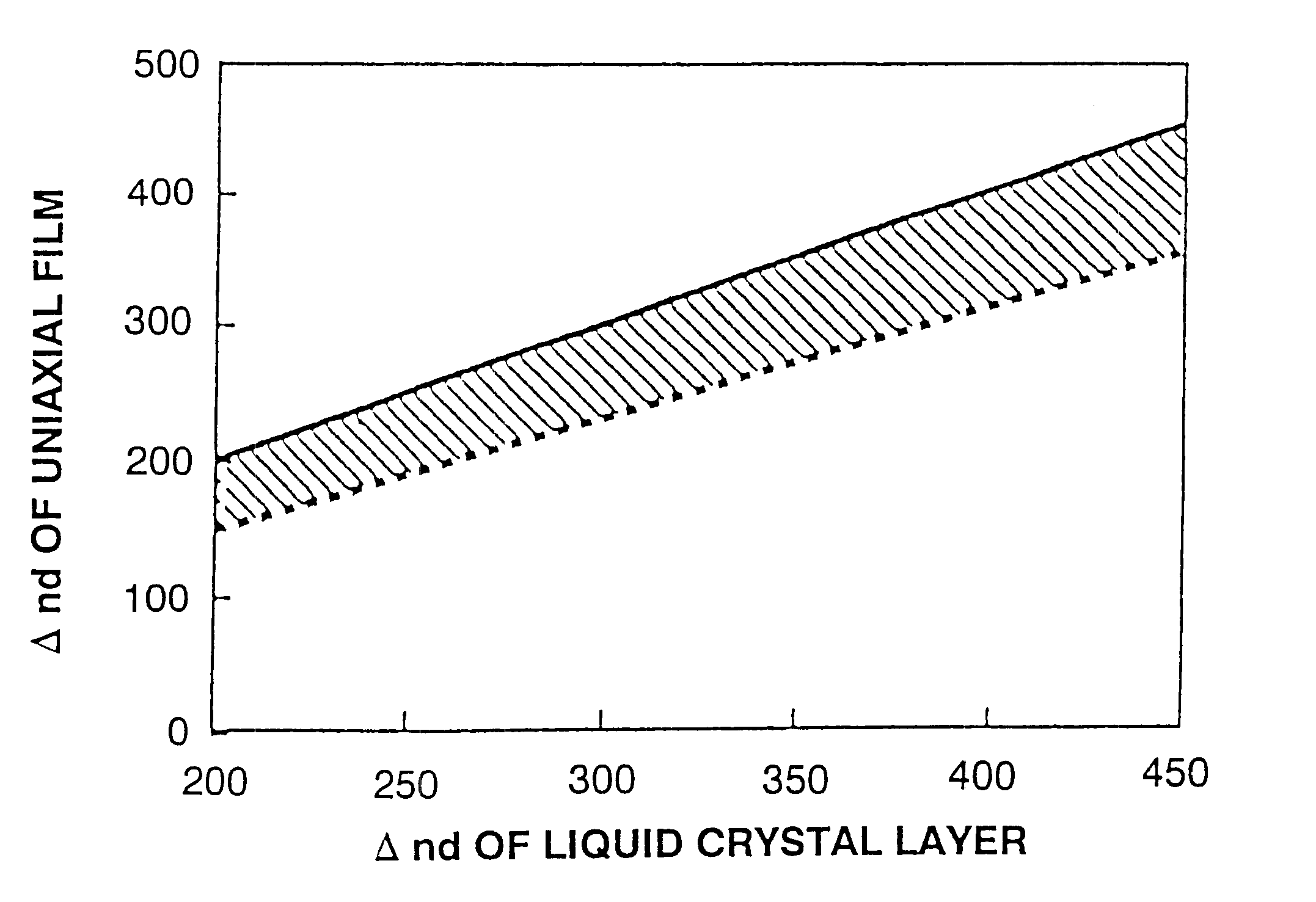
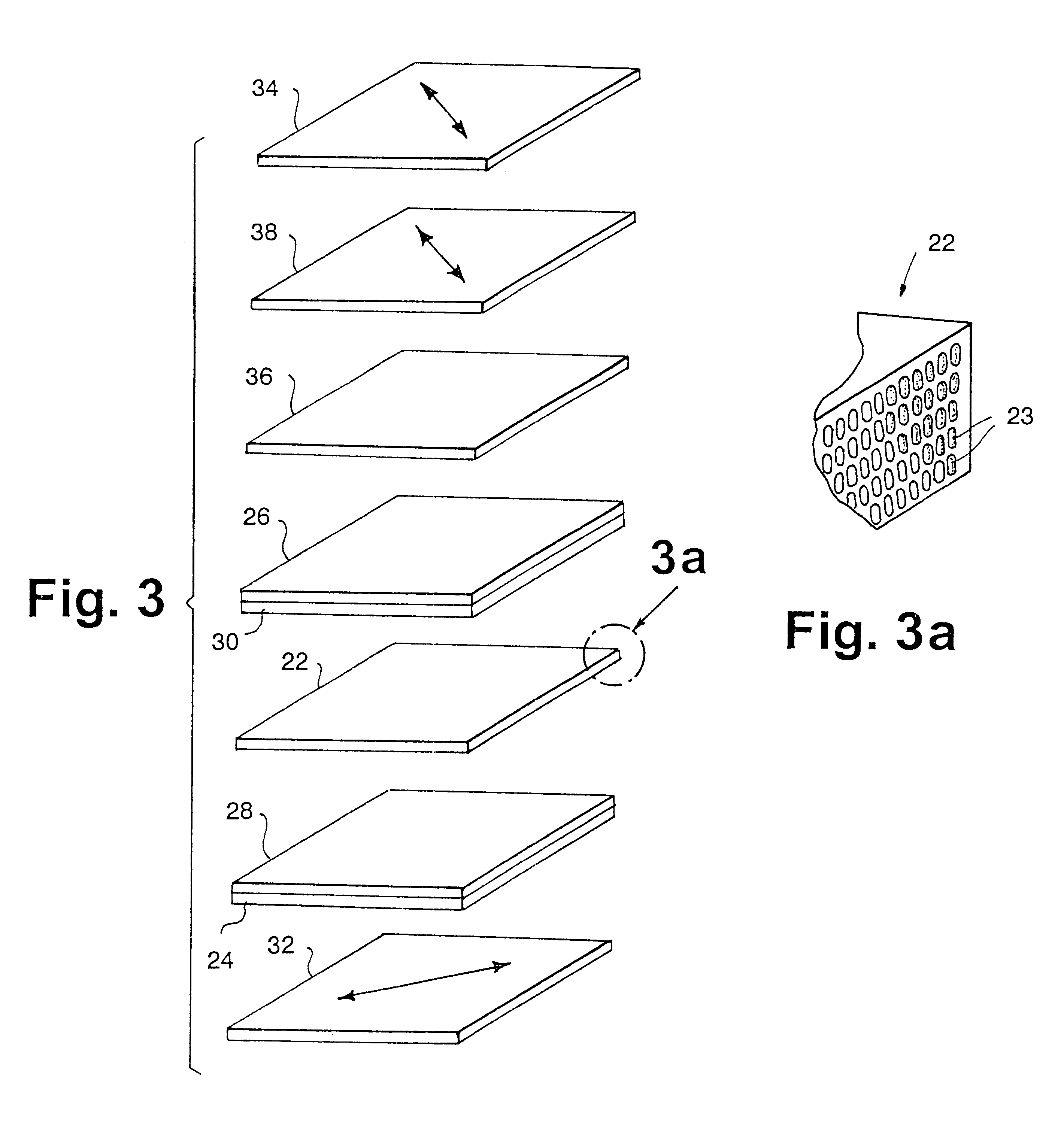
A vertical alignment liquid crystal display device capable of a complete contrast compensation, particularly by performing an optical compensation using an optically uniaxial anisotropic sheet and an optically biaxial anisotropic sheet. A retardation of the optically uniaxial anisotropic sheet should have an opposite sign to the retardation of a liquid crystal layer, and absolute value of the retardation of the optically uniaxial anisotropic sheet should be within the range of 75 to 100% of the retardation of the liquid crystal layer. The optically uniaxial anisotropic sheet may be united with a polarizing plate. The optically biaxial anisotropic sheet should have a retardation axis which is parallel to a transmitting axis of any one of the polarizing plates. The optically biaxial anisotropic sheet should exhibit an in-plane retardation of 190 to 390 nm, and exhibit a retardation of 0.28 to 0.67 in its thickness direction. The resulting vertical alignment liquid display device has a high contrast even when viewed from an oblique direction.

Description

1. Technical FieldThe present invention relates to an active matrix type liquid crystal display device, more particularly to a so-called vertical alignment mode liquid crystal display device in which an electric field in a vertical direction is applied to a liquid crystal layer having liquid crystal molecules possessing a negative dielectric anisotropy, the molecules being oriented in the vertical direction, and the liquid crystal molecules are allowed to orient in a horizontal direction, thus controlling a light transmission / cutting-off.2. Prior ArtA widely spread conventional display device using liquid crystal materials employs a liquid crystal layer of a twisted nematic liquid crystal. In this device, an electric field is applied in a direction perpendicular to the substrate. In this system, polarizing plates are arranged on the two sides of the liquid crystal layer in such a way that their polarizing axes are perpendicular. Liquid crystal molecules are oriented in a vertical di...

Claims


Application Information

Patent Timeline
IPC IPC(8): G02F1/13G02F1/139G02B5/30G02F1/13363G02F1/1335
CPCG02F1/13363G02F1/1393G02F1/133634G02F2413/12G02F2413/02G02F2413/08G02F2202/40G02F1/1335
Inventor SAITOH, YUKITO
Owner SHIN KOH DEN TECH LTD
Why Eureka
Try Eureka