Method of using a retarder plate to improve contrast in a reflective imaging system

Inactive Publication Date: 2002-01-22
JDS UNIPHASE CORP
View PDF12 Cites 93 Cited by
  • Summary
  • Abstract
  • Description
  • Claims
  • Application Information

AI Technical Summary

Benefits of technology

Waveplate retarder 640 is optically coupled to the second surface 623b of substrate 623, multi-layer optical interference coating 621 being disposed on the first surface 623a of substrate 623. Thus waveplate retarder 640 is tilted from normal incidence with respect to the second optical axis 602. Waveplate retarder 640 has a predetermined retardance value to compensate for the rotation and ellipticity induced by at least one of polarizing element 603 and dichroic mirrors 610 and 620 thereby increasing the contrast of the third, or green, color channel.
FIG. 7 illustrates an additional embodiment illustrating utility in a field sequential color imaging system. The illumination 705, polarization 703 and spatial light modulation 730, and projection elements 750 are arranged as depicted in FIG. 7 merely to illustrate the operative principles, and should not be construed as limiting. In a field sequential color imaging system the viewer perceives a continuous full color image over the entire viewing or image field via the rapid present

Problems solved by technology

We have discovered that the conventional means for reducing the Fresnel reflection from a waveplate retarder is unsatisfactory in that an unmodulated reflected signal from a waveplate retarder associated with a particular color

Method used


Image

  • Method of using a retarder plate to improve contrast in a reflective imaging system
  • Method of using a retarder plate to improve contrast in a reflective imaging system
  • Method of using a retarder plate to improve contrast in a reflective imaging system

Examples


Embodiment Construction

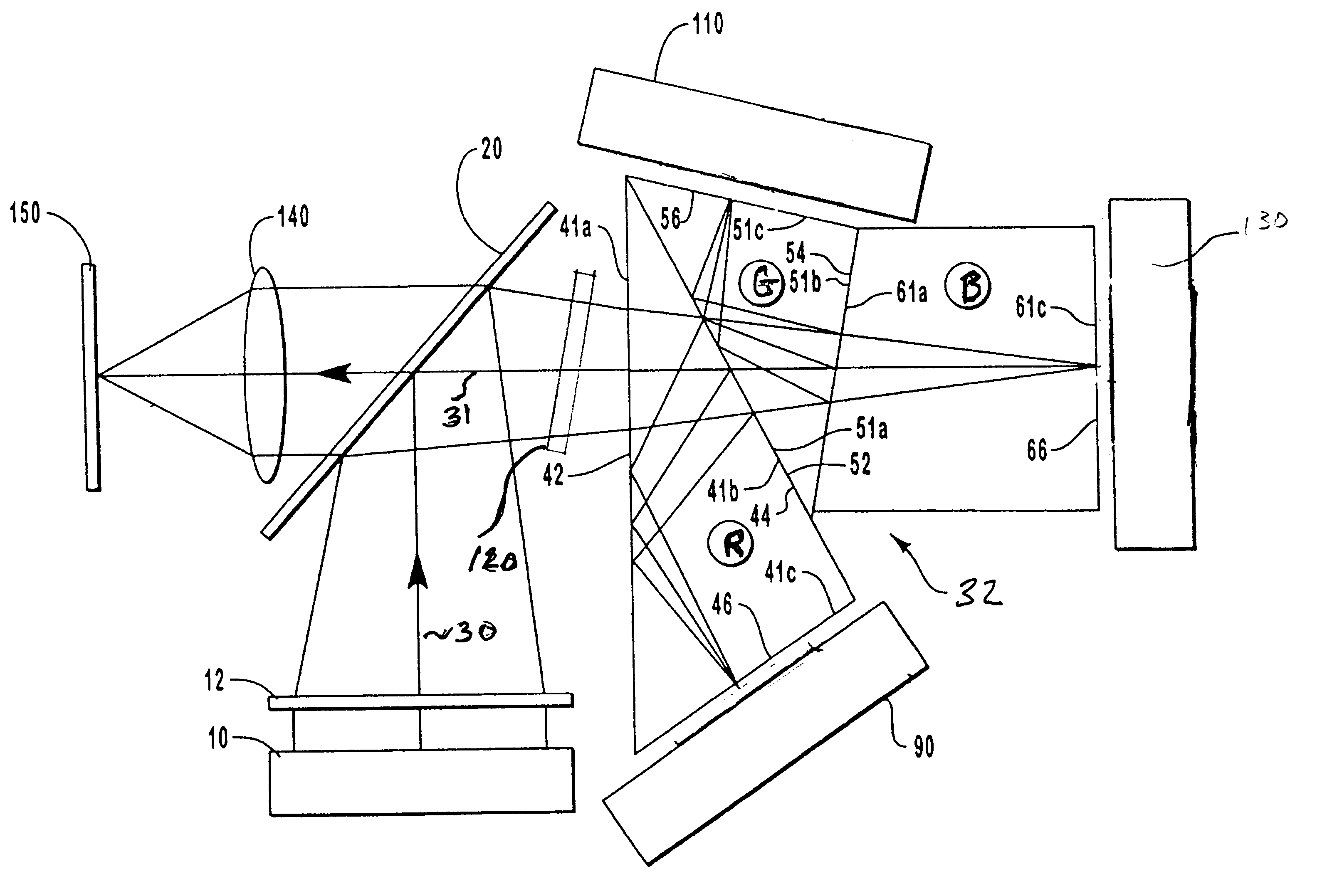
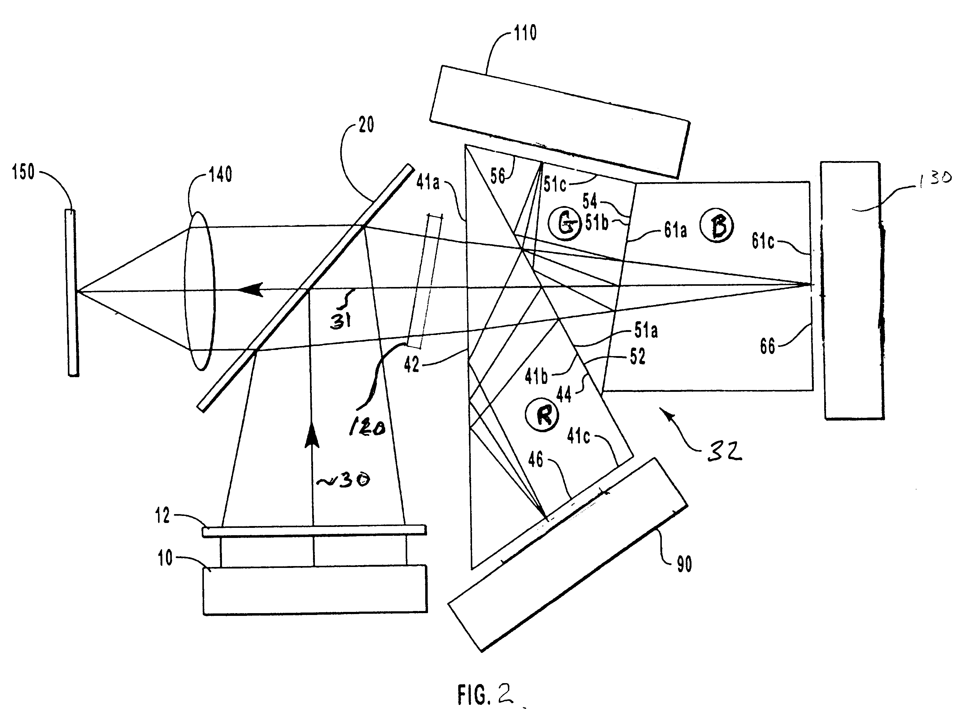
This example of a preferred embodiment illustrates the construction of the prism corresponding to the green color channel as illustrated in FIG. 5. The waveplate retarder 120 has a retardance of 80 nm and is laminated to a glass plate 140, the glass plate having a thickness of 3 mm. The resulting waveplate and glass laminate is in turn attached or bonded directly onto prism G , thereby fixing the waveplate retarder 120 between the glass plate 140 and prism G. This assembly configuration and method fixes the angle of incidence of the second optical axis with respect to waveplate retarder 120 at about 10 degrees. Waveplate retarder 120 is effectively embedded within the color separation device, such as philips prism 32 in FIG. 4 which comprises prisms G, R and B. The thickness of prism G in the direction of the second optical axis is adjusted to accommodate the thickness of the waveplate, glass plate and any optical adhesive 160; the optical adhesive being utilized at one or more of t...


PUM


Abstract

Methods and apparatus for enhancing the performance of a reflective liquid crystal display system. The high-contrast color splitting prism system utilizes a "double-passed" prism assembly. Polarized light enters the prism assembly, is color-split and emitted as separate colors to spatial light modulators which reflect each color in accordance with a desired image. The reflective light is passed, once again, through the prism assembly where the separate colors converge and propagate to a projection lens for display of the image on a screen. A waveplate retarder is positioned between the liquid crystal display and the polarizing element. The waveplate retarder is tilted with respect to the optical axis to eliminate the deleterious effects of the Fresnel reflections at the interfaces of the waveplate retarder.

Description

1. The Field of the InventionThe present invention is directed to systems, methods and apparatus for achieving enhanced contrast in reflective imaging systems, such as those utilizing reflective liquid crystal display imagers and color splitting devices, such as Philips prisms. The invention maximizes the transmission of light polarized in a certain direction while minimizing the transmission of light polarized in another direction, thereby achieving a high contrast ratio which significantly improves the final image quality.2. The Relevant TechnologyLiquid crystal displays are commonly used as spatial light modulators in projection imaging systems. A reflecting type of liquid crystal panel (which is also known as a liquid crystal light valve) comprises an array of pixels, which when activated works by reflecting incident light while simultaneously rotating the polarization vector of the light by 90 degrees, typically when a voltage or signal is applied to an individual pixel. Thus t...

Claims


Application Information

Patent Timeline
IPC IPC(8): G02B27/28H04N9/31H04N5/74
CPCG02B27/283H04N9/3197H04N9/3102H04N5/7441
Inventor BRYARS, BRETT J.GREENBERG, MICHAEL R.SULLIVAN, SEAN
Owner JDS UNIPHASE CORP
Why Eureka
Try Eureka