
Process and plant for the production of urea with high conversion yield and low energy consumption

Inactive Publication Date: 2002-01-29
UREA CASALE SA
View PDF10 Cites 11 Cited by
  • Summary
  • Abstract
  • Description
  • Claims
  • Application Information

AI Technical Summary

Benefits of technology

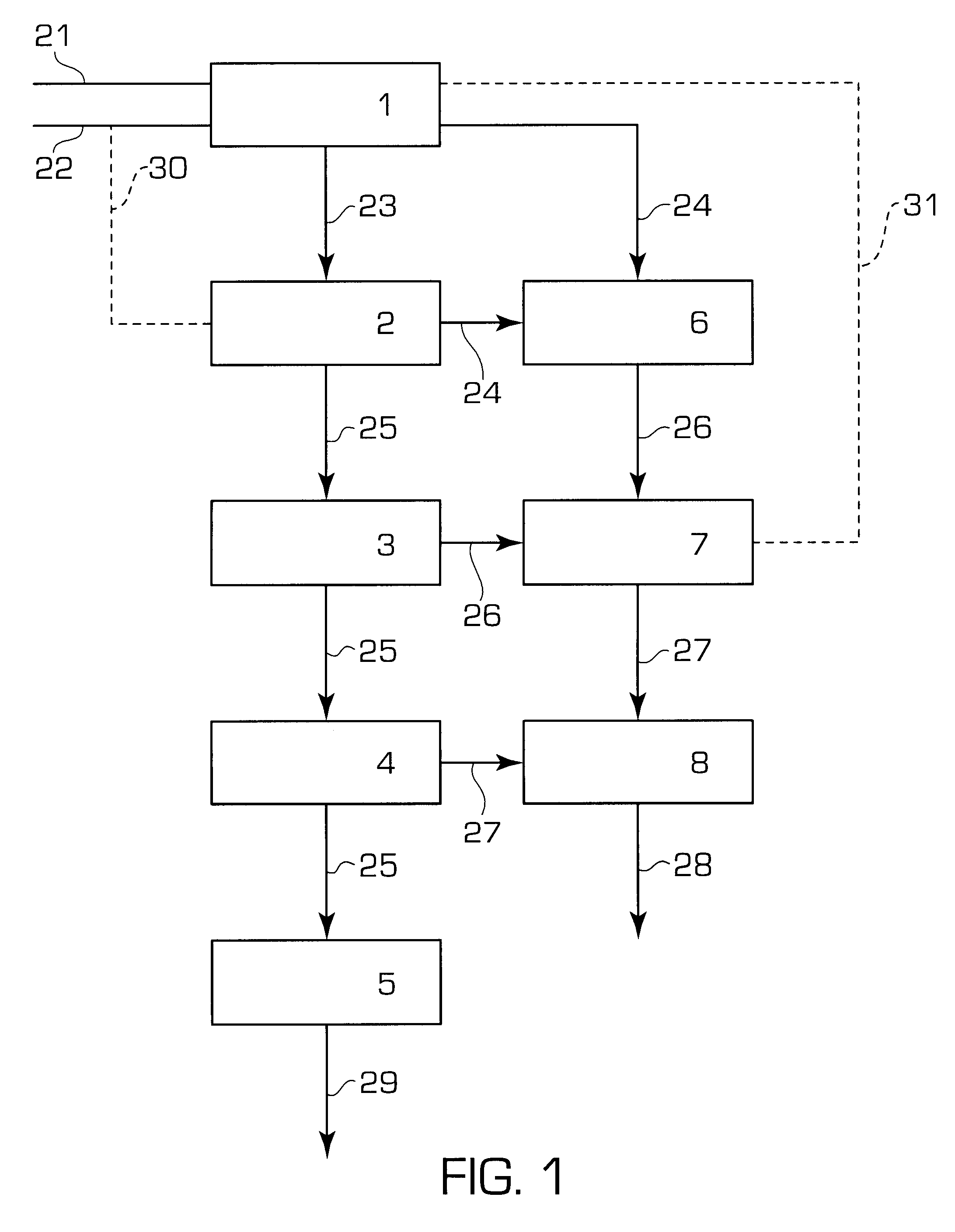
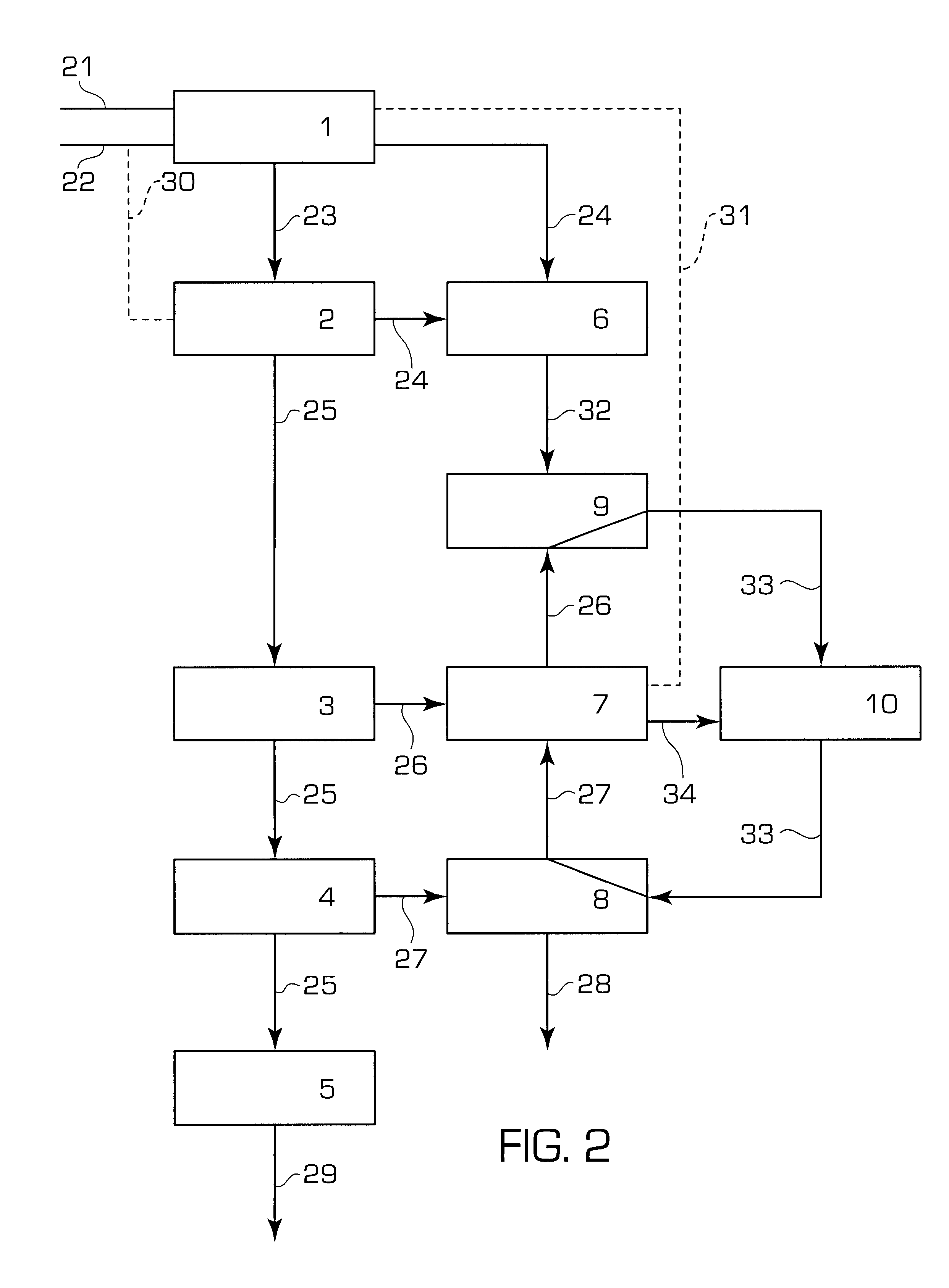
So doing, the unreacted substances which are recycled to the reaction space have a very low water content, and thus it is possible to substantially limit the water fed to the reaction space, permitting a high conversion yield.
In accordance with this embodiment, the implementation of the urea production process is technically very simple, since no relevant additional equipment is required compared to the prior art processes, and it involves low investment costs.
In accordance with the present invention the plants delegated to carry out the urea production process may be provided either new or by modifying pre-existing plants so as to obtain a production capacity expansion and at the same time improved performance from the energy consumption viewpoint.

Problems solved by technology

If, on the one hand, this recycle allows almost complete recovery of valuable substances such as ammonia and carbon dioxide, on the other hand it also involves the sending to the reactor of large quantities of water (H.sub.2 O) which are detrimental to the overall yield of conversion of the carbon dioxide to urea, with the yield being generally between 59% and 63%.

Method used


Image

  • Process and plant for the production of urea with high conversion yield and low energy consumption
  • Process and plant for the production of urea with high conversion yield and low energy consumption
  • Process and plant for the production of urea with high conversion yield and low energy consumption

Examples


example 2

A pre-existing plant operating according to the prior art process described with reference to FIG. 1 is modernized in order to operate according to the process described with reference to FIG. 2.

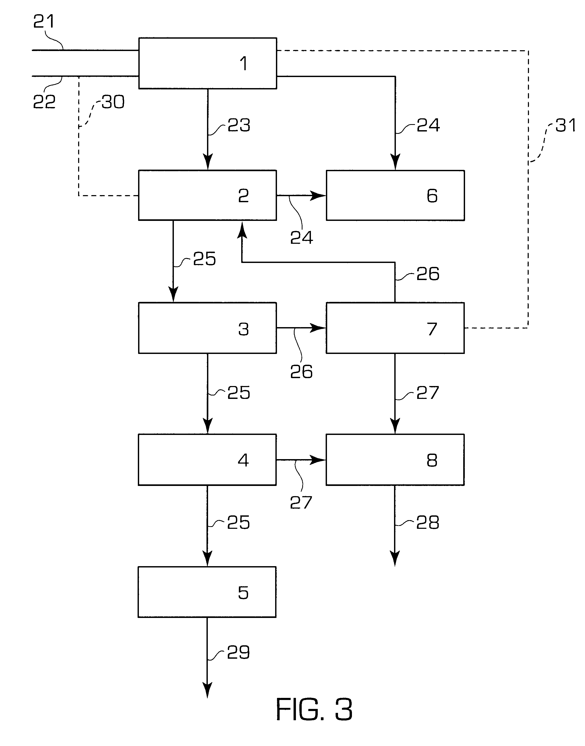
The pre-existing plant is based on the carbon dioxide stripping process, wherein a flow of carbon dioxide as stripping agent is fed to the decompostion unit indicated by block 2 (flow line 30). In this case, the ammonia separation unit comprised in block 7 and flow line 31 are missing. Also units 3 and 7 are missing, and the urea recovery section only comprises the low pressure units 4 and 8.

The operation conditions of the urea synthesis reactor before the plant modernization are the followings:

molar ratio NH.sub.3 / CO.sub.2 at input: 3.0;

molar ratio H.sub.2 O / CO.sub.2 at input: 0.5;

conversion yield of the CO.sub.2 into urea: about 60%;

pressure: about 145 bar a;

temperature: 185.degree. C.;

capacity: 1900 MTD urea

After modernizing the pre-existing plant by providing a second stripping unit 9 f...

example 3

In this example, the conversion yield of a reactor operating in a brand new plant implementing the process according to the present invention as described in FIG. 2 has been simulated.

As for the above example 2, the plant is based on the carbon dioxide stripping process, wherein all the carbon dioxide to be fed to the reactor 1 is first fed as stripping agent in the decompostion unit indicated by block 2 through flow line 30. In this case, flow line 22 is missing as well as the ammonia separation unit comprised in block 7 and flow line 31. The urea recovery section comprises the medium and low pressure units 3, 4, 7 and 8.

The operation conditions of the reactor in the urea production plant according to the present invention are the followings:

molar ratio NH.sub.3 / CO.sub.2 at input: 3.2;

molar ratio H.sub.2 O / CO.sub.2 at input: 0.1;

pressure: about 150 bar a;

temperature: 190.degree. C.;

capacity: 400 MTD urea

The conversion yield of the CO.sub.2 into urea obtained by the present reactor...


PUM

PropertyMeasurementUnit
Fractionaaaaaaaaaa
Fractionaaaaaaaaaa
Fractionaaaaaaaaaa

Abstract

In a process for the production of urea, substantially pure ammonia and carbon dioxide are reacted in a reaction space (1) from which comes out a reaction mixture subjected to stripping (2) to obtain a partially purified mixture sent to a urea recovery section (3, 4, 7, 8). From the recovery section (3, 4, 7, 8) it is obtained a dilute carbamate solution, which is subjected to stripping (9) with recycling of vapors to the reaction space (1) after condensation (6). This process achieves high conversion yield with reduced energy consumption and low implementation costs.

Description

In its general aspect the present invention relates to a process for urea production.The present invention relates specifically to a process for urea production of the type comprising the steps of:performing a reaction between ammonia and carbon dioxide in a reaction space to obtain a reaction mixture comprising urea, carbamate and free ammonia in aqueous solution;subjecting said mixture to a treatment of partial decomposition of the carbamate and partial separation of said free ammonia in aqueous solution to obtain a first flow comprising ammonia and carbon dioxide in vapor phase and a flow comprising urea and residual carbamate in aqueous solution;subjecting said first flow comprising ammonia and carbon dioxide in vapor phase to at least partial condensation to obtain a first portion of carbamate in aqueous solution;recycling said first portion of carbamate to said reaction space;feeding said flow comprising urea and residual carbamate in aqueous solution to a urea recovery sectio...

Claims


Application Information

Patent Timeline
IPC IPC(8): C07C273/00C07C273/04B01J12/02C07C275/00
CPCC07C273/04Y02P20/582
Inventor PAGANI, GIORGIOZARDI, UMBERTO
Owner UREA CASALE SA
Learn More