Time correlated photon counting

a technology of time-correlated photons and counting, applied in the direction of fluorescence/phosphorescence, luminescent dosimeters, optical radiation measurement, etc., can solve the problems of difficult determination, and inability to accurately time pulses outside this rang

Inactive Publication Date: 2002-01-29
IBM CORP
View PDF10 Cites 60 Cited by
  • Summary
  • Abstract
  • Description
  • Claims
  • Application Information

AI Technical Summary

Problems solved by technology

However, for SPDs, this determination can be difficult because of the variation in the amplitude and the shape of the electrical pulses associated with detected photons.
However this a-priori assumption that the shape the electrical pulse created by each detected photon stays constant is only approximately valid for only a very limited range of varying pulse amplitudes.
However, this approximation is valid only over a limited range of pulse amplitudes, and pulses outside this range are not accurately timed.
At best, t...

Method used


Image

  • Time correlated photon counting
  • Time correlated photon counting
  • Time correlated photon counting

Examples


Embodiment Construction

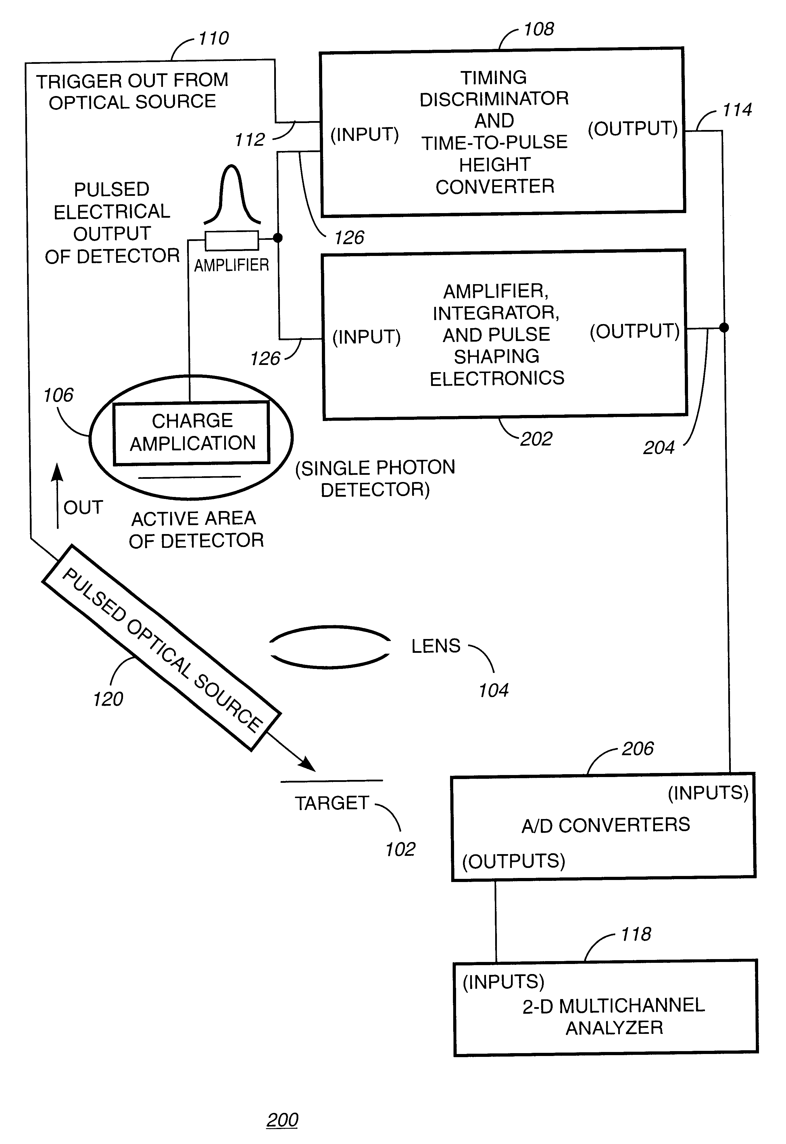
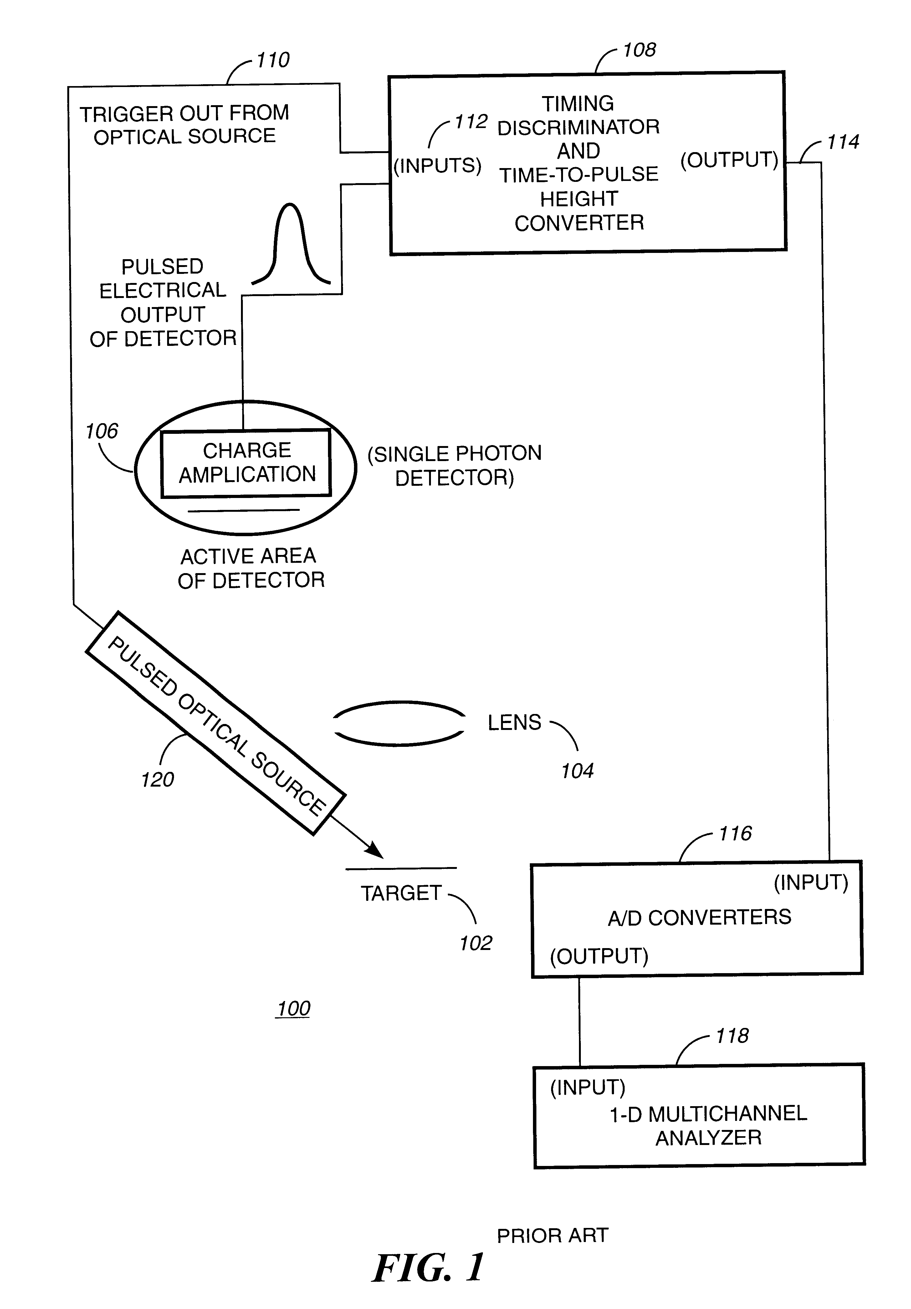
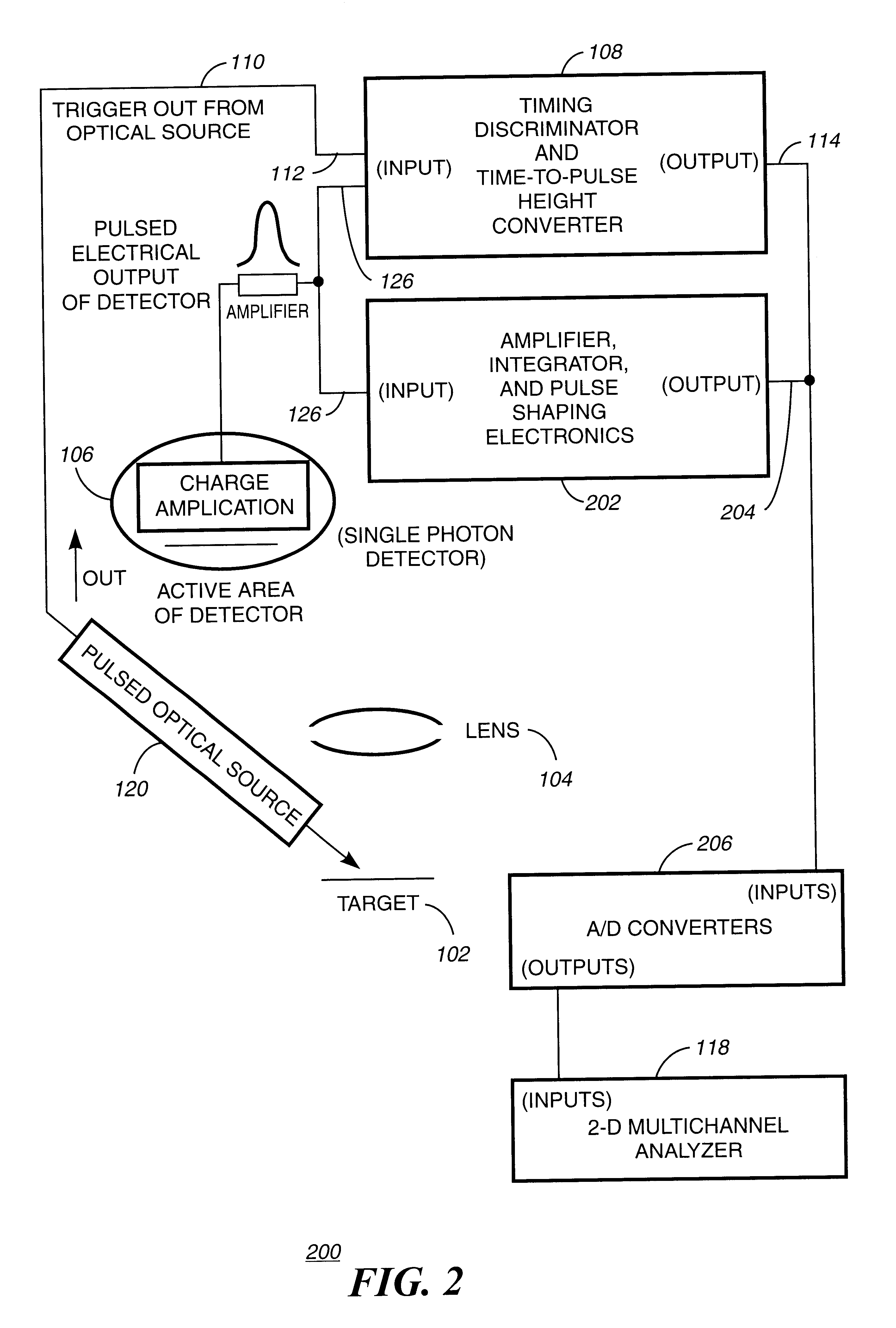
Referring now in more detail to the drawings in which like numerals refer to like parts throughout the several views, FIG. 2 is a functional block diagram of an improved TCPC time and integrated amplitude system 200 using a typical TCPC single photon detection system as system 100 of FIG. 1, with additional electronics according to the present invention. An amplifier, integrator and pulse shaping electronics, hereinafter simply referred to as pulse shaping electronics 202 are placed in a parallel path to converter 108. The pulse shaping electronics 202 has an input 126 which is coupled to the output of the single photon detector SPD 106. An output 204 is coupled to an A / D converter 206. In the system 200 the electrical pulses from each photon as read by detector 106 are characterized by a time difference as described in FIG. 1. The time difference is represented by an analog electrical pulse series of difference signals, each with respective maxima and whose magnitude is related to ...


PUM


Abstract

A system for time-correlated photon counting. The system uses one or more photon detectors to produce electrical pulses corresponding to photons read from a target. The system uses a discriminator with a first input coupled to a trigger output from a pulsed optical source and a second input for receiving the electrical pulses. A time-to-pulse height converter is used for producing a series of difference signals each with a respective maxima and whose magnitude is related to the time difference between the trigger output and the electrical pulses. In addition, the system employs a pulse shaping electronic circuit for receiving pulsed electrical output and producing a series of one or more characteristic signals. An A/D converter with a first input receives the difference signals and a second input receives part of the characteristic signals. The A/D converter produces a first series of digital signals representing the difference signals and a second series of digital signals representing the characteristics signals. The results of the A/D converter are feed to a multichannel analyzer for time-shifting the first series of digital signals based on at the second series of digital signals so that the maxima for any given difference signals occurs at the same time as the maxima for at least one other part of the series of the difference signals.

Description

Not applicable1. Field of the InventionThe invention disclosed broadly relates to the field of time-resolved photon emission and more particularly relates to the field of fast single photon detection and counting and timing.2. Description of the Related ArtThe use of single photon counting for both analytical tools and research continues to increase. Time correlated photon counting TCPC) (also known as time correlated single photon counting or photon timing) has been known for many years, as described in the article entitled "Single-Photon Timing Detectors For Fluorescence Lifetime Spectroscopy" by Graham Hungerford and David J. S. Birch on pp.121-135 of Measurement Science Technology 7 (1996), printed in the UK. FIG. 1 illustrates a conventional TCPC time correlated single photon detection (SPD) counting system 100. A target 102 to be sampled is placed under a lens 104. A pulsed optical source 120 emits a short pulse of photons which is focused onto a target 102. Note that neither ...

Claims


Application Information

Patent Timeline
IPC IPC(8): G01N21/64G01J3/28G01J3/44
CPCG01J3/2889G01N21/6408G01J3/4406
Inventor KASH, JEFFREY A.
Owner IBM CORP
Why Eureka
Try Eureka