
Arrangement for controlling floating drilling and intervention vessels

Inactive Publication Date: 2002-02-05
MERCUR SLIMHOLE DRILLING & INTERVENTION
View PDF14 Cites 67 Cited by
  • Summary
  • Abstract
  • Description
  • Claims
  • Application Information

AI Technical Summary

Benefits of technology

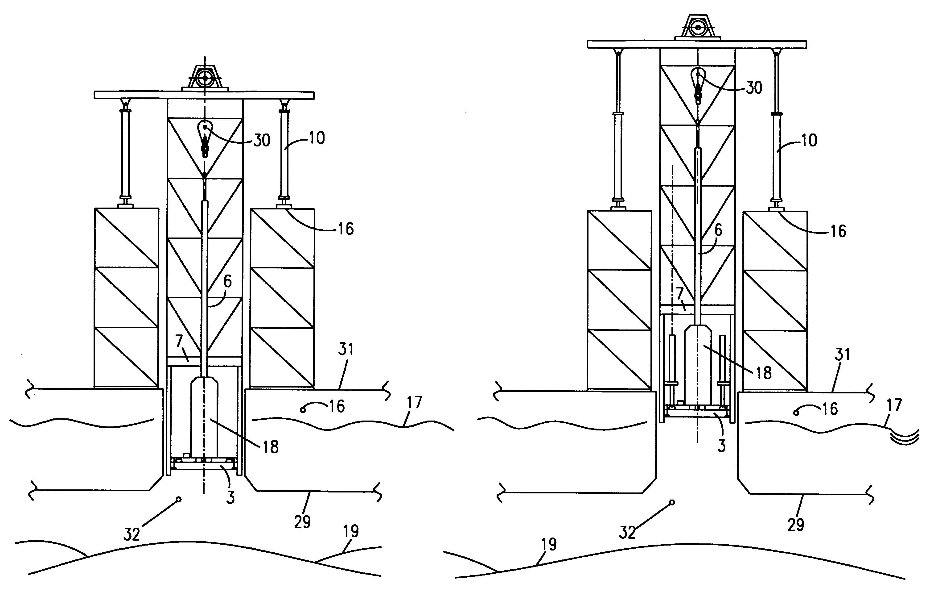
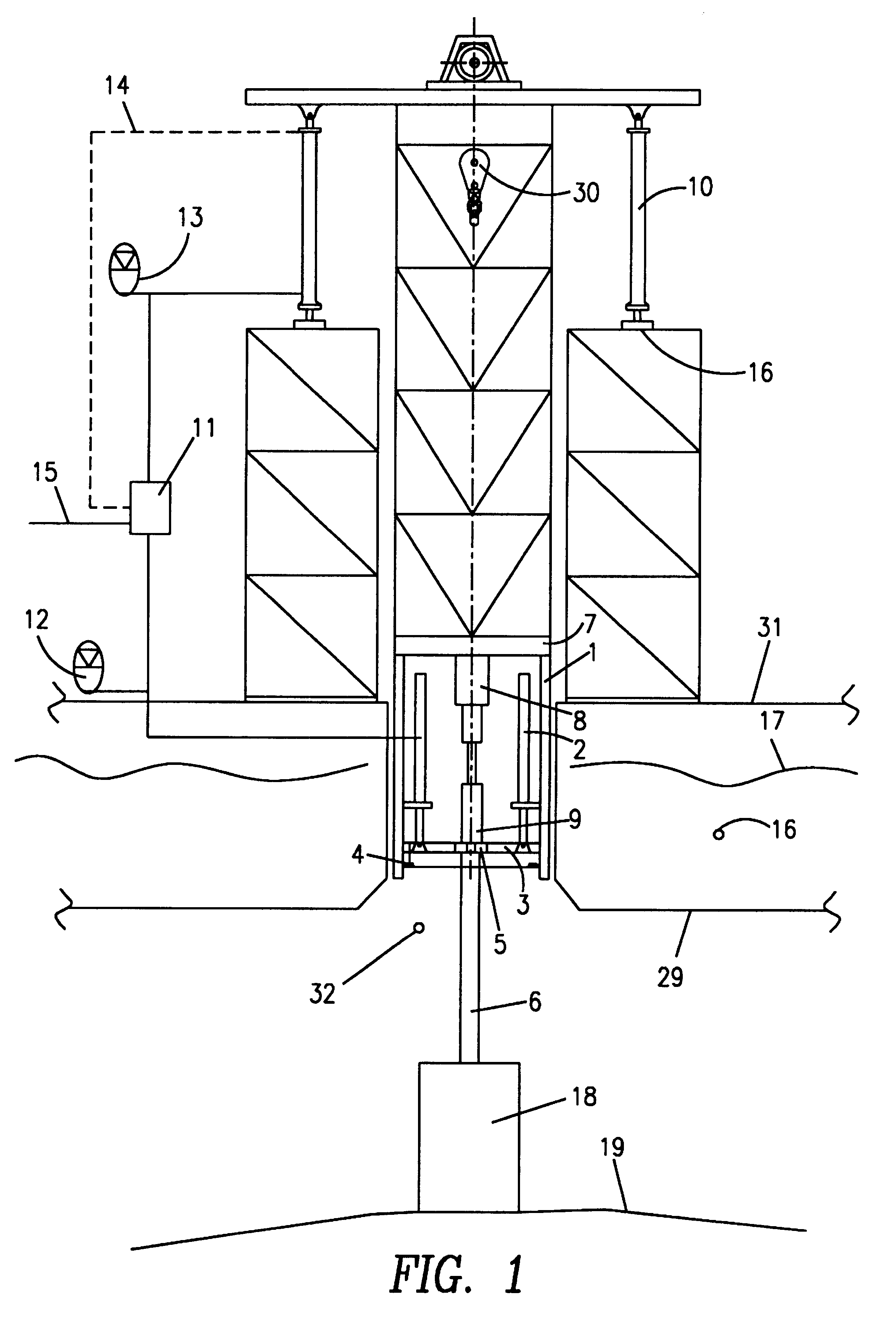
The arrangement is installed in a drilling and intervention vessel 16. The vessel comprises a moon pool 32. This is an opening in the hull through which tools like a drill string etc. can be lowered into the sea. In the figure a riser pipe system 6 is shown passing through the moon pool 32 and down to the sea bottom 19. The drilling unit comprises a drill floor 7 with a derrick. At the top of the derrick the draw works are installed. The whole unit is suspended by means of hydraulic heave compensator cylinders 10. The cylinders are coupled to a hydraulic circuit, which causes the cylinders to expand and contract in unison with the movements of the vessel. In this way the rolling of the vessel is compensated, so that the drilling crew is working in a stable environment without movement caused by the surrounding seas.

Problems solved by technology

However, the maintenance of this system is both complicated and dangerous.
Current arrangements for drilling and well service from floating appliances have no arrangements which neutralise the influence of the tide on the drilling system.
Thus this operation has evident limitations with regard to the safety of the personnel and the lifetime of the coiling tubes, and it makes slim hole drilling from floating appliances difficult.
This means that the system must operate with error margins and tolerances that are unacceptable for slim hole operations and compensated drill floors.

Method used


Image

  • Arrangement for controlling floating drilling and intervention vessels
  • Arrangement for controlling floating drilling and intervention vessels
  • Arrangement for controlling floating drilling and intervention vessels

Examples


Embodiment Construction

FIG. 1 shows an embodiment of an arrangement according to the invention for neutralising the tidal influence on a drill floor compensator system.

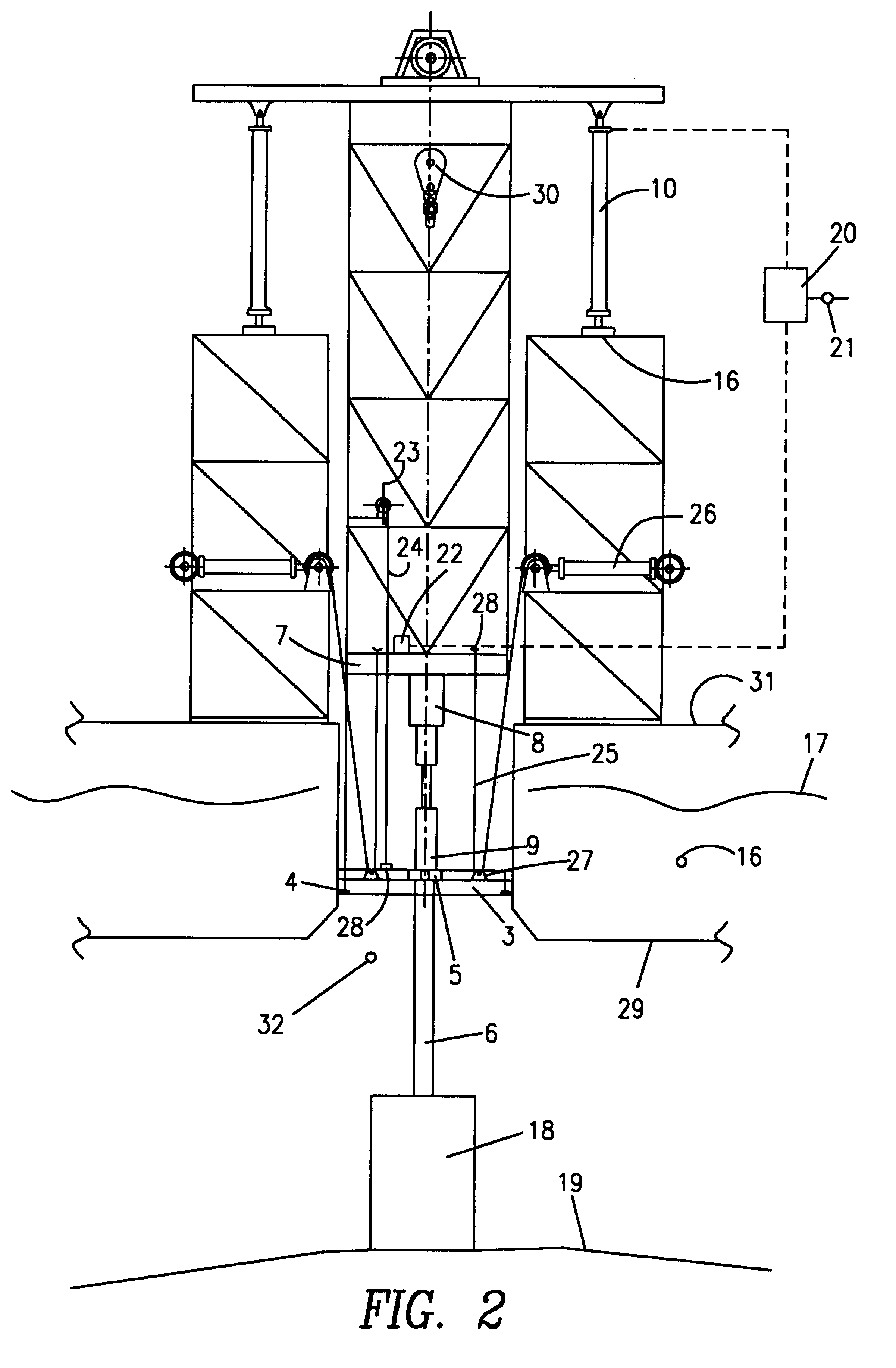
The arrangement is installed in a drilling and intervention vessel 16. The vessel comprises a moon pool 32. This is an opening in the hull through which tools like a drill string etc. can be lowered into the sea. In the figure a riser pipe system 6 is shown passing through the moon pool 32 and down to the sea bottom 19. The drilling unit comprises a drill floor 7 with a derrick. At the top of the derrick the draw works are installed. The whole unit is suspended by means of hydraulic heave compensator cylinders 10. The cylinders are coupled to a hydraulic circuit, which causes the cylinders to expand and contract in unison with the movements of the vessel. In this way the rolling of the vessel is compensated, so that the drilling crew is working in a stable environment without movement caused by the surrounding seas.

The arrangement according...


PUM


Abstract

The present invention relates to an arrangement in a floating drilling and intervention vessel, for controlling a heave compensated drill floor 7 suspended in drill floor compensator cylinders 10. Below the compensated drill floor 7 there is installed a tidal structure (3) suspended in tidal cylinders 2 or wires 25. By adjusting the tidal cylinders 2 or the wires 25 in step with the tide 17 it is achieved that the drill floor compensator cylinders 10 can operate around their middle position regardless of the tide lifting or lowering the vessel 16.

Description

The present invention relates to an arrangement for controlling a compensated drill floor on a floating drilling or intervention vessel, which is a vessel for carrying out well drilling, completion, workover and / or production operations at the sea. The invention acts to neutralise tidal influence on the position of the drill floor in relation to the sea bottom.PRIOR ARTFloating drilling and intervention vessels must have some means to compensate for the heave exerted on the vessel by the sea.Large floating drilling rigs traditionally include a telescopic coupling device in the riser / drill string. The coupling devices are placed below the drill floor, which means that the drill crew can work almost without regard to the continuously changing influence of the sea. However, the maintenance of this system is both complicated and dangerous.Many drilling vessels have installed a system where the complete drill floor with derrick is heave-compensated. The floor is mounted on hydraulic cyli...

Claims


Application Information

Patent Timeline
IPC IPC(8): E21B19/00B63B35/44
CPCE21B19/006E21B19/002B63B35/4413
Inventor GLEDITSCH, SVEIN
Owner MERCUR SLIMHOLE DRILLING & INTERVENTION
Learn More