Oscillator and radio equipment
a radio equipment and oscillator technology, applied in the direction of reradiation, instruments, and the details of the semiconductor/solid-state device, can solve the problems of difficult to achieve coupling between the dielectric line, easy generation of unwanted electromagnetic fields, and difficulty in obtaining an oscillator of smaller size with these devices
- Summary
- Abstract
- Description
- Claims
- Application Information
AI Technical Summary
Problems solved by technology
Method used
Image
Examples
first embodiment
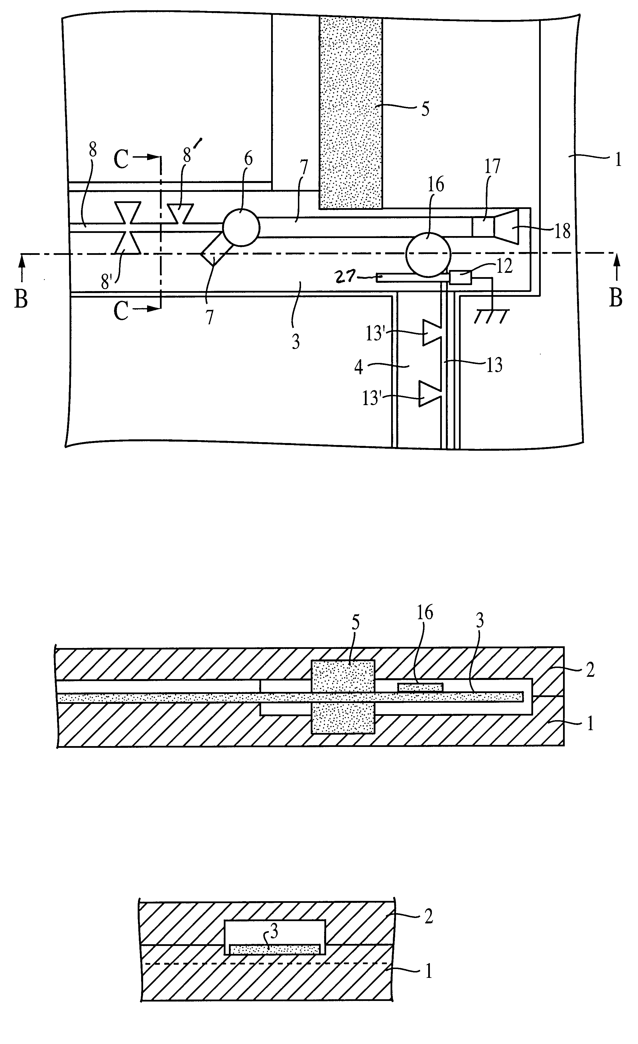
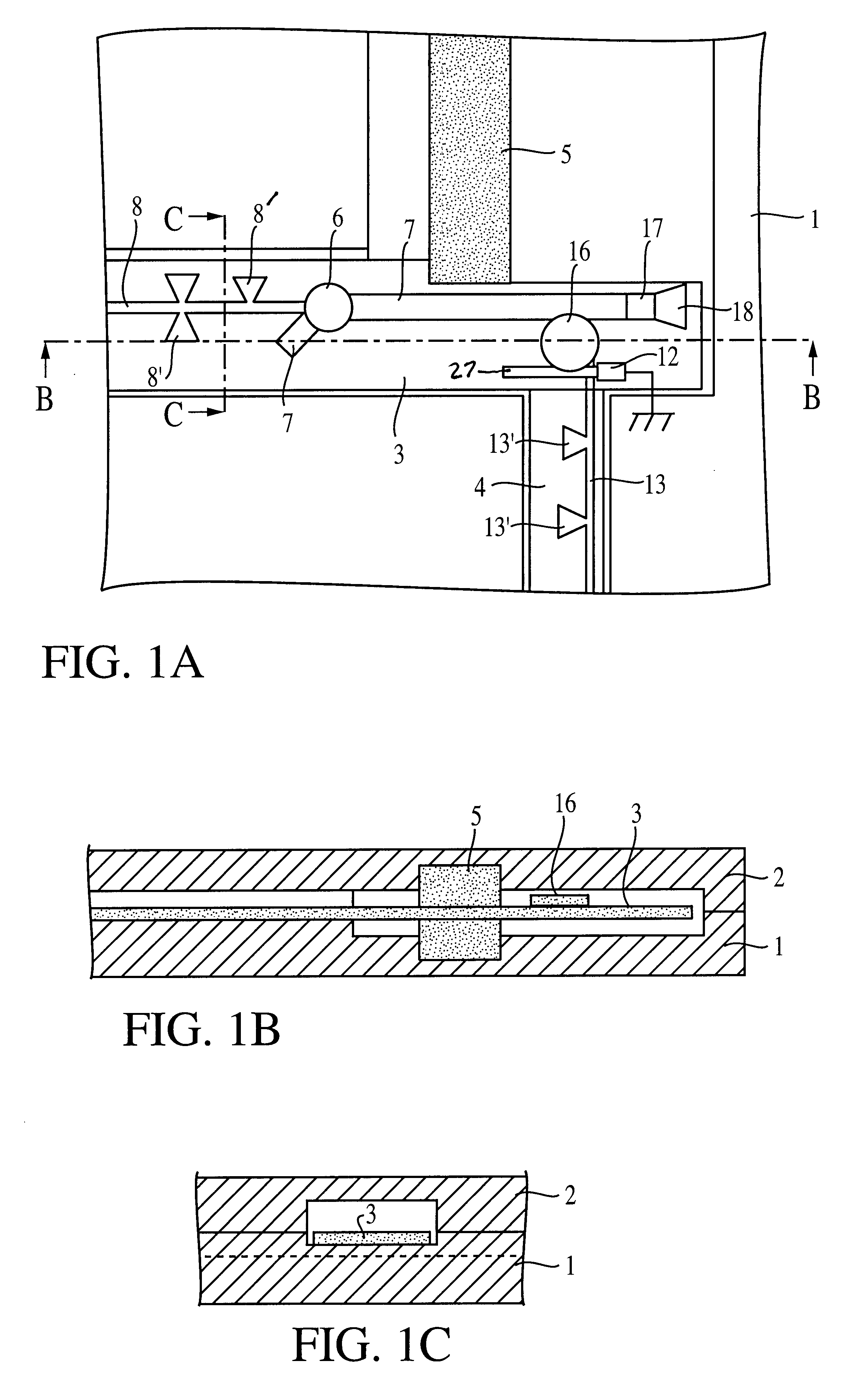
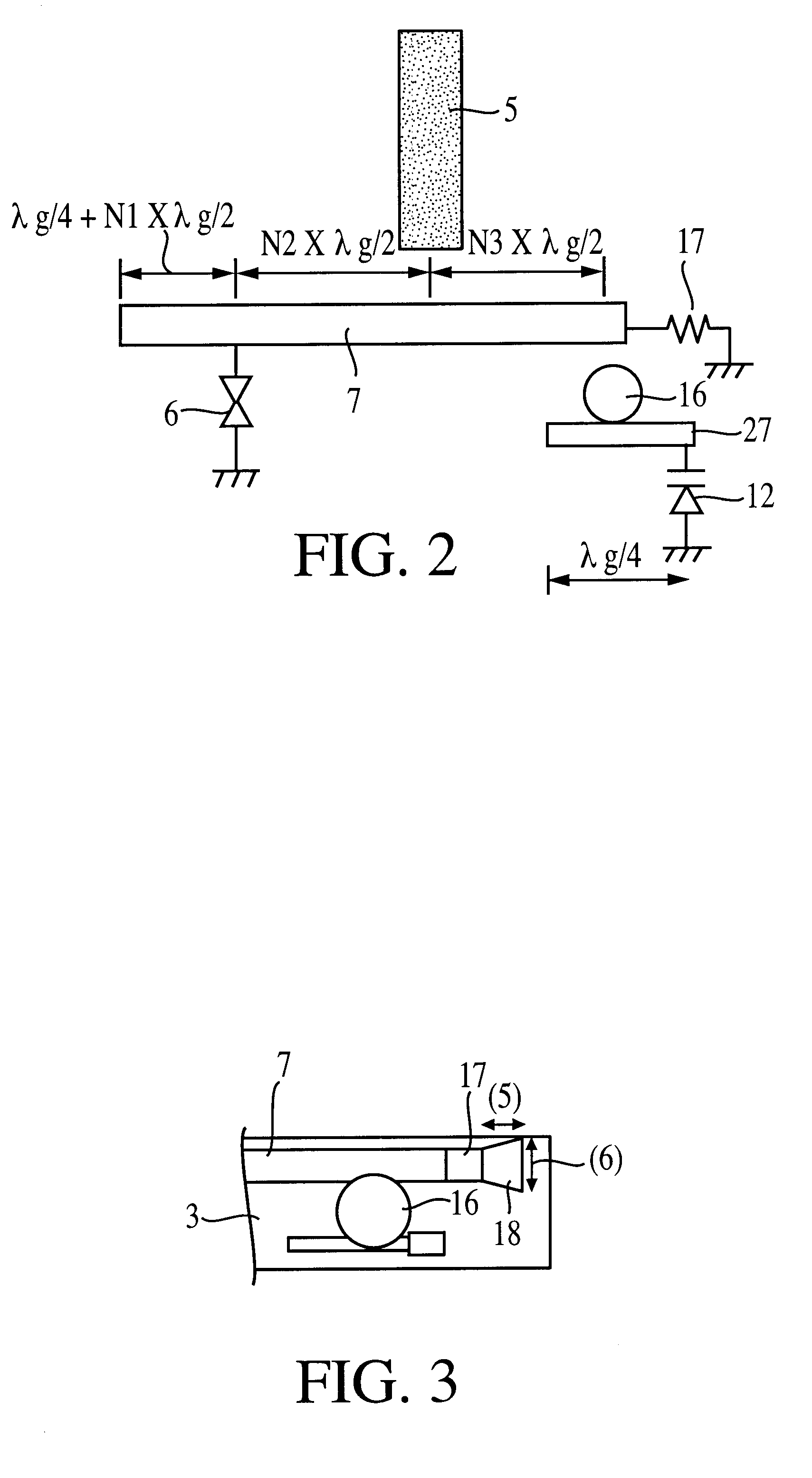
The construction of an oscillator is described with reference to FIGS. 1A, 1B, 1C, 2, and 3.
FIG. 1A is a top view of an oscillator having upper and lower conductor plates in which the upper conductor plate is removed, FIG. 1B is a sectional view taken on line B--B in FIG. 1A, and FIG. 1C is a sectional view taken on line C--C in FIG. 1A. In FIGS. 1A to 1C, a lower conductor plate I and an upper conductor plate 2 are shown, and inside a space sandwiched between these upper and lower conductor plates an oscillator is constructed. In the drawings, dielectric substrates 3 and 4 are shown. A line 7 for an oscillation circuit is provided on the upper surface of the dielectric substrate 3, and a Gunn diode 6 is connected at a fixed location in the line 7. The Gunn diode 6 is of a pill package type and is mounted on the lower conductor plate 1, and an electrode which projects from the Gunn diode 6 passes through a hole formed in the dielectric substrate 3 and is electrically connected to t...
third embodiment
FIG. 5 is a top view of an oscillator having upper and lower conductor plates in which the upper conductor is removed. Unlike the oscillator shown in FIGS. 1A, 1B, and 1C, in the third embodiment, the cutoff frequency of an NRD guide made up of a dielectric stripline 5 and upper and lower conductor plates 1 and 2 is determined so that the fundamental wave component of an oscillation signal from an oscillation circuit is cut off and the component of the second harmonic or higher harmonic is transmitted. When 38 GHz, for example, is the fundamental oscillation frequency of a Gunn diode 6, 76 GHz as its second harmonic is transmitted to the NRD guide.
Unlike the case of the first embodiment shown in FIG. 1A, a stub 9 for harmonics and a stub 10 for the fundamental wave are provided in a bias line 8. FIG. 6 shows the construction of that portion. The stub 9 is provided at a location a distance (1) apart from the location of the Guun diode 6, and the length of the stub 9 from the connecti...
fourth embodiment
Next, the construction of an oscillator is shown in FIG. 7. FIG. 7 is a top view of the oscillator in which an upper conductor plate is removed. Unlike the example shown in FIG. 1, on the dielectric substrate 3, an electrode 21 and an adjustment terminal 20 are provided. Furthermore, in this example, no voltage-controlled variable frequency circuit is provided.
In FIG. 7, by weakly coupling the electrode 21 to the line 7 and by connecting a spectrum analyzer, etc. to the adjustment terminal 20, it is possible to monitor an oscillation signal. In order to adjust the oscillation frequency, for example, the portion T of one open end of the line 7 is trimmed so that the frequency of the fundamental wave becomes half of the frequency of the second harmonic which is actually used.
In this way, as the electrode 21 is only weakly coupled to the line 7, the electrode 21 does not adversely affect anything else. Furthermore, because the electrode 21 is weakly coupled to the line 7 where the fun...
PUM
 Abstract
Description
Claims
Application Information
 - R&D
- Intellectual Property
- Life Sciences
- Materials
- Tech Scout
- Unparalleled Data Quality
- Higher Quality Content
- 60% Fewer Hallucinations
Browse by: Latest US Patents, China's latest patents, Technical Efficacy Thesaurus, Application Domain, Technology Topic, Popular Technical Reports.
© 2025 PatSnap. All rights reserved.Legal|Privacy policy|Modern Slavery Act Transparency Statement|Sitemap|About US| Contact US: help@patsnap.com


