Open-lattice, foldable, self-deployable structure

a self-deployable, foldable technology, applied in the direction of flooring, transportation and packaging, cosmonautic vehicles, etc., can solve the problems of difficult application of self-deployment to ultra-low density requirements of lightly loaded structures, mechanisms that provide the deployment become parasitic mass, and general structural inefficiency of hinge or latch mechanisms of these mechanical systems

Inactive Publication Date: 2002-02-12
FOSTER-MILLER
View PDF40 Cites 49 Cited by
  • Summary
  • Abstract
  • Description
  • Claims
  • Application Information

AI Technical Summary

Benefits of technology

It is a further object of this invention to provide such a structure which is reliable.
It is a further object of this invention to provide such a structure which does not require any hinge, latch, or actuator mechanisms which would add par

Problems solved by technology

Mechanical systems, however, have both theoretical and practical limitations that make it difficult to apply them to ultra-low density requirements of lightly loaded structures.
In a mechanical deployment system, the mechanisms that provide the deployment become parasitic mass once the deployment is complete.
The hinge or latch mechanisms of these mechanical systems are also generally structurally inefficient and there are practical limitations to how small such a mechanism can reasonably be fabricated and still be reliable.
Moreover, the parasitic mass added by the hinges, latches, and actuators reduces overall system performance, limiting the acceleration of solar sails, for example.
This means that the structure is more massive than it theoretically has to be, thus increasing the costs of delivering the spacecraft.
Although such inflatable systems offer the potential of very low mass and very high packaging efficiency for missions that have low ultimate load requirements, there are again both theoretical and practical limitations that have thus far proven to be significant limitations to the use of inflatable systems as compressive structural elements.
Prior research has shown that the effects of even minor localized deviations from the ideal shape can greatly reduce the stiffness and strength of the resultant column.
Moreover, inflatable structures suffer from the limitation that low level leaks and micro-meteoroid punctures can eventually drain the gas to the point that the structures can no longer hold their shape.
Moreover, the gas used to provide this internal pressure adds to the non-structural launch mass of the system.
Compounding this mass problem is the issue that it is

Method used


Image

  • Open-lattice, foldable, self-deployable structure
  • Open-lattice, foldable, self-deployable structure
  • Open-lattice, foldable, self-deployable structure

Examples


Embodiment Construction

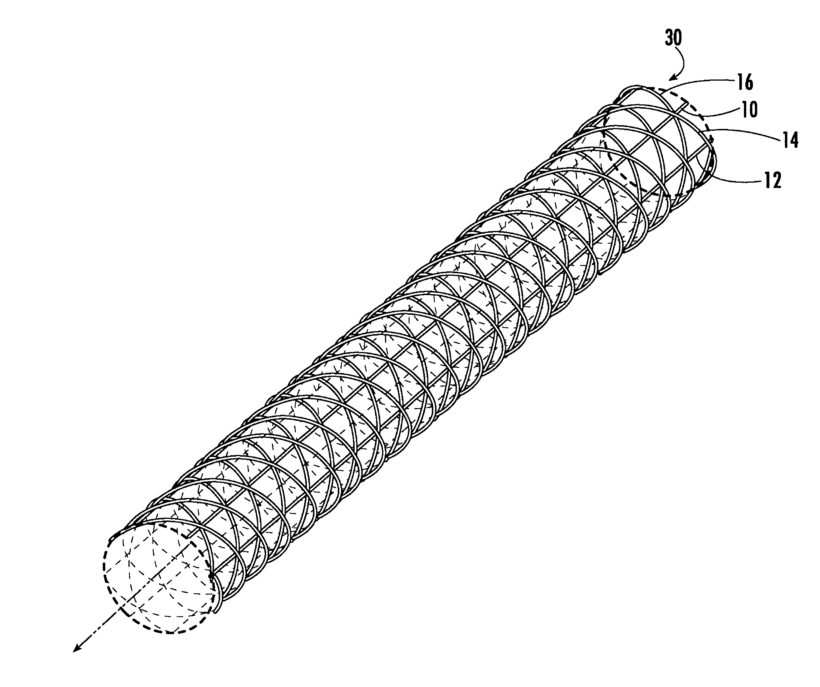
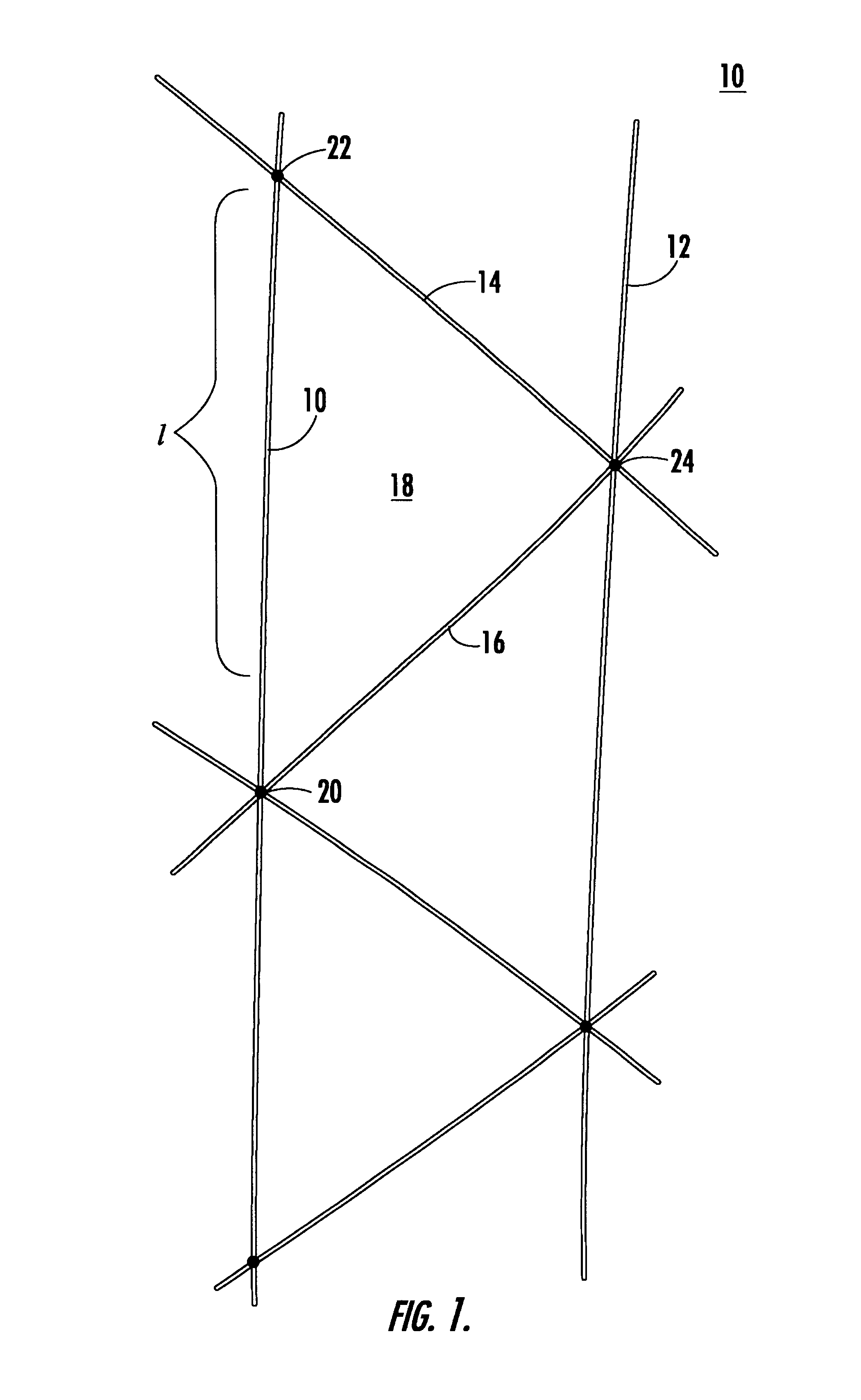
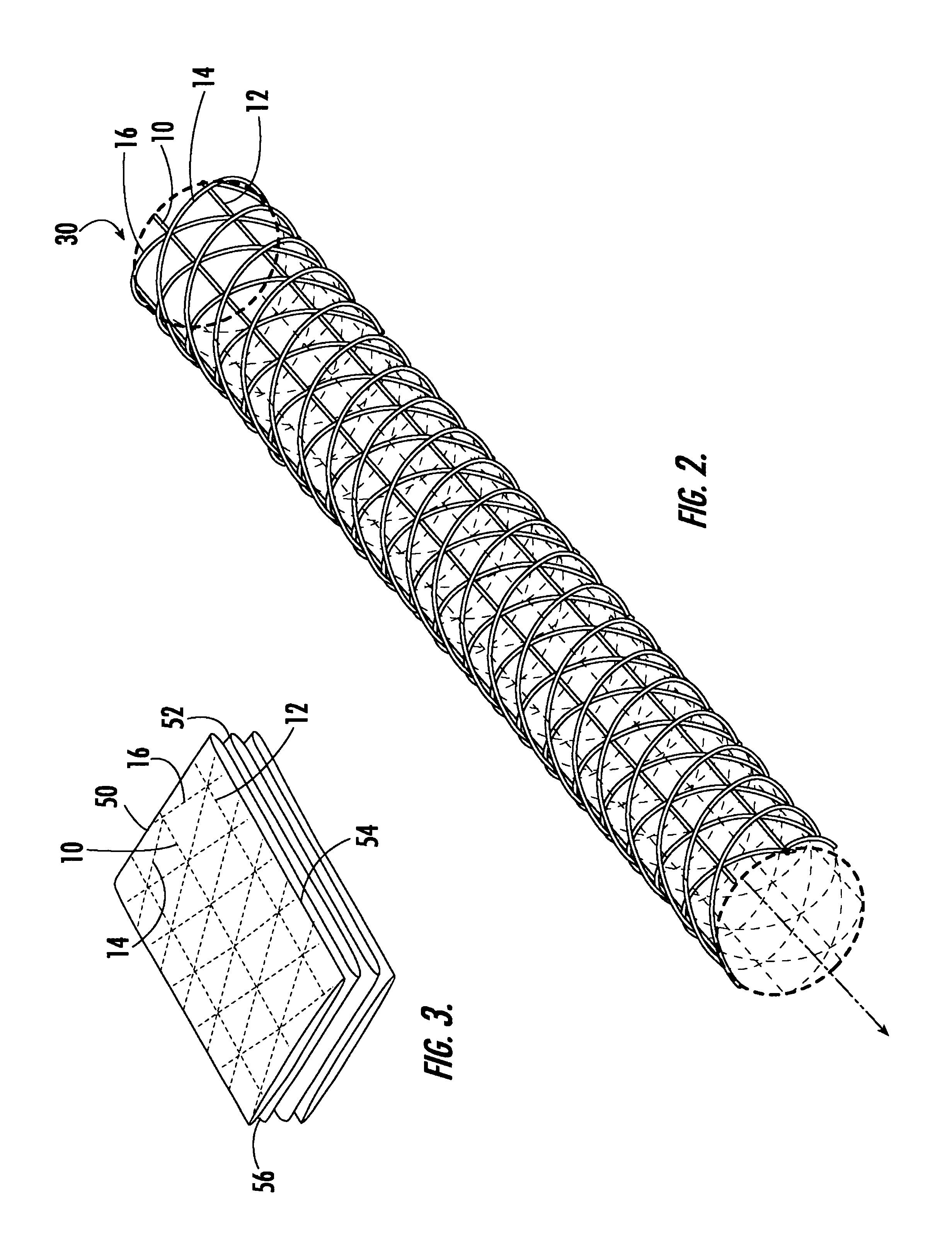
Structure 10, FIG. 1 includes spaced longitudinal members 10, 12 and spaced diagonal members 14, 16 as shown spanning between longitudinal members 10 and 12. Thus, structure 10 is an open-lattice structure including open cells such as cell 18 bounded by portions of longitudinal members 10 and 12 and diagonal members 14 and 16. There are some means for joining diagonal members 14 and 16 to longitudinal members 10 and 12 at selected cell boundary intersection points 20, 22, and 24. Such means include adhesives, pins, rivets, and the like or as discussed infra respect to FIG. 12.

The cells may take the shape of an isosceles triangle as shown for cell 18 with apexes 20, 22, and 24 each including the intersection of two diagonal members 14 and 16 with a longitudinal member 10, 12 although this is not a necessary limitation of the present invention.

NASA Technical Memorandum 78687, hereby incorporated herein by this reference, discusses the mechanical characteristics of such structures in g...


PUM


Abstract

An open-lattice, foldable, self-deployable structure with a number of spaced, bendable longitudinal members forming cells each bounded by a portion of two spaced longitudinal members and two spaced diagonal members. The diagonal members are joined to the longitudinal members at the cell boundary intersections of the diagonal members and the longitudinal members. The longitudinal members are made of a material which bends by a predetermined amount below the material's yield point and the diagonal members are made of a material which both bends and twists by a predetermined amount below the material's yield point so that the structure can be collapsed and then self resurrected.

Description

FIELD OF THE INVENTIONThis invention features an open-lattice, foldable, self-deployable structure which can be used for solar sails, heat shields, communication devices, sensors and sensor arrays, power generation devices, and the like.BACKGROUND OF INVENTIONUltra-light weight, large spacecraft structures can be used for a variety of purposes including solar sails, heat shields, communication devices, power generation devices, and the like. The structures must be compatible for deployment, self deployable, and upon deployment, sufficiently rigid and stable and unfolding to a shape exactly the same as it was before it was folded compactly for deployment in space. In the prior art, mechanical systems and inflatable systems were used.Mechanical deployment systems are among the best understood of prior art spacecraft mechanisms. See U.S. Pat. No. 4,579,302 incorporated herein by this reference. Virtually all spacecraft mechanically deploy at least one component to gather solar power, r...

Claims


Application Information

Patent Timeline
IPC IPC(8): B64G9/00B64G1/22E04B1/19B64G99/00
CPCB64G1/222B64G9/00E04B1/19E04B2001/1924E04B2001/1987E04B2001/1954E04B2001/1972E04B2001/1975E04B2001/1984E04B2001/1951B64G99/00
Inventor WARREN, PETER A.
Owner FOSTER-MILLER
Why Eureka
Try Eureka