Vehicle wheel construction process

a technology of vehicle wheels and construction processes, applied in the field of composite wheel assemblies, can solve the problems of difficult plate chromium plating, high cost of adhesive tapes, and general prohibitive mass production cost of such adhesive tapes

Inactive Publication Date: 2002-02-12
LACKS INDUSTRIES INC
View PDF39 Cites 55 Cited by
  • Summary
  • Abstract
  • Description
  • Claims
  • Application Information

AI Technical Summary

Benefits of technology

, the wheel, overlay and selective application of the localized nests of the present invention create a sealed mold of the cavity between the wheel and the overlay for the foam to expand in to. The nests and the sealant bead, in combination with the clamping system, provide adequate sealing to prevent foam from escaping through any of the openings in the wheel disc. There is no need to add sleeves and covers, trim away excess foam from the wheel assembly, or clean up any foam scrap from the manufacturing equipment and area.

Problems solved by technology

Overlays are not only employed to improve the appearance of unadorned standard steel wheels, but are also used with cast aluminum wheels, that are known to be expensive and difficult to plate with chromium.
), the cost of such adhesive tapes is generally prohibitive for use in mass production applications such as securing an overlay to a wheel.
Consequently, such applications are generally limited to the use of less expensive adhesive tapes that have relatively low maximum operating temperatures, necessitating that their placement be restricted to the radially outward surfaces of the wheel.
Unfortunately, doing so severely limits the adhesive tape's ability to reliably adhere the overlay to the wheel.
Further, the use of adhesive tape because of its defined thickness creates a void between the overlay and the wheel that can collect dirt and debris that may affect the balance of the wheel.
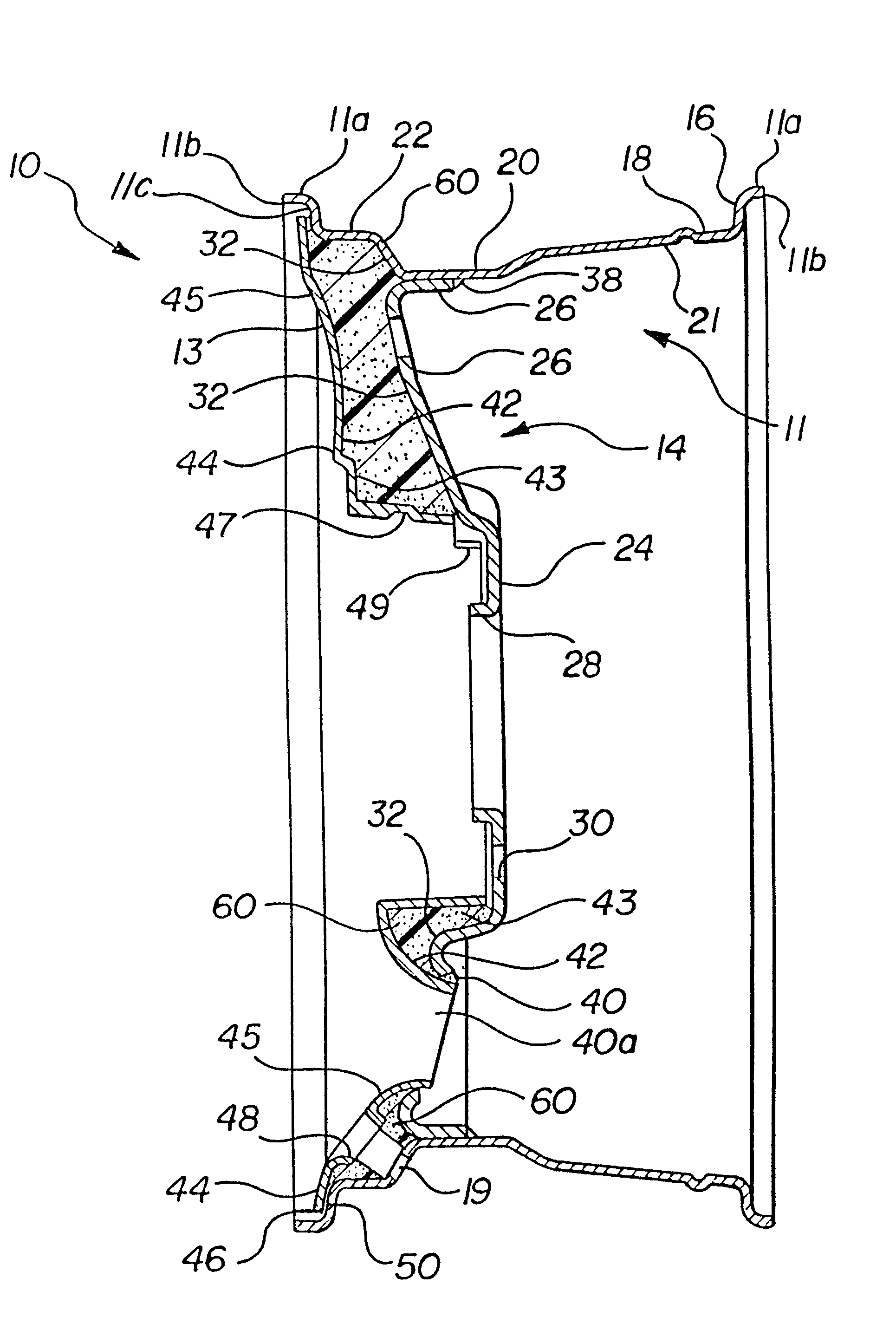
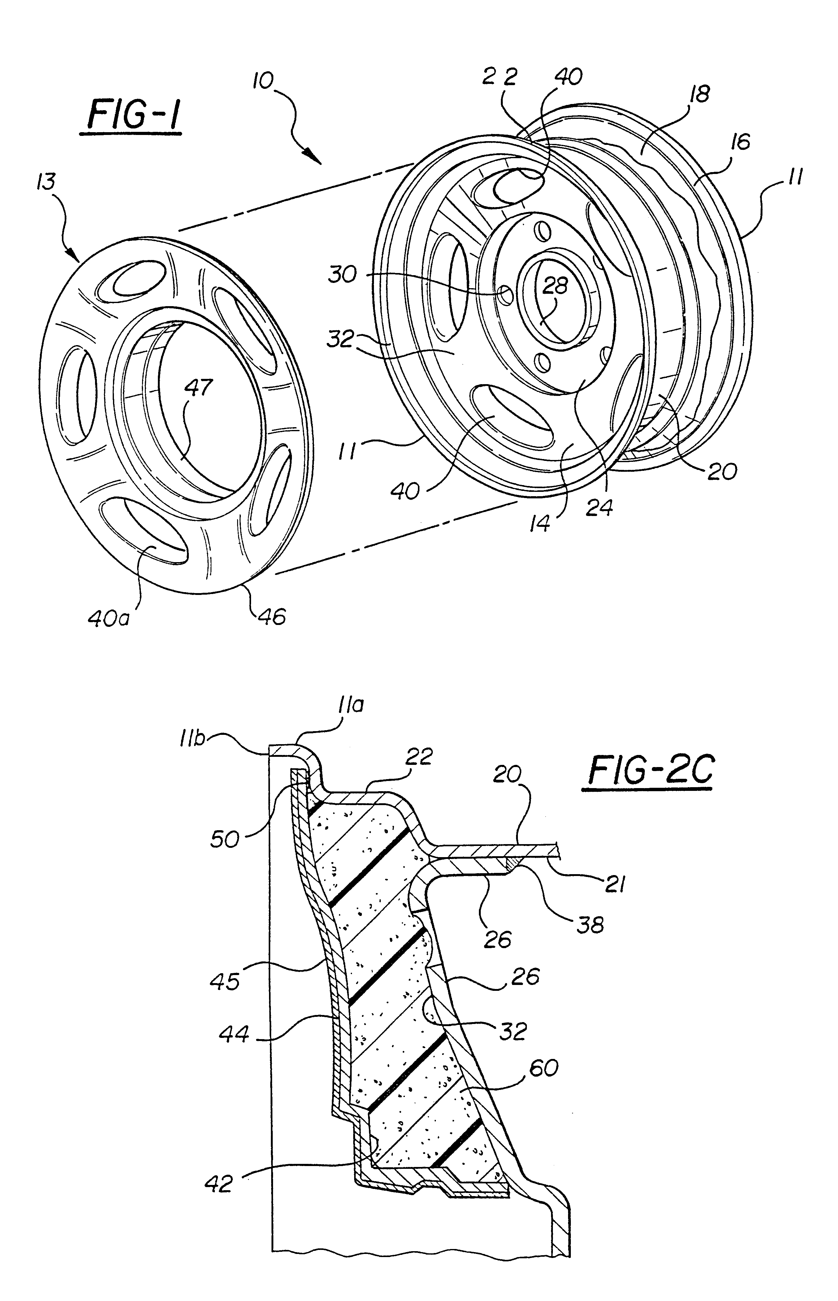
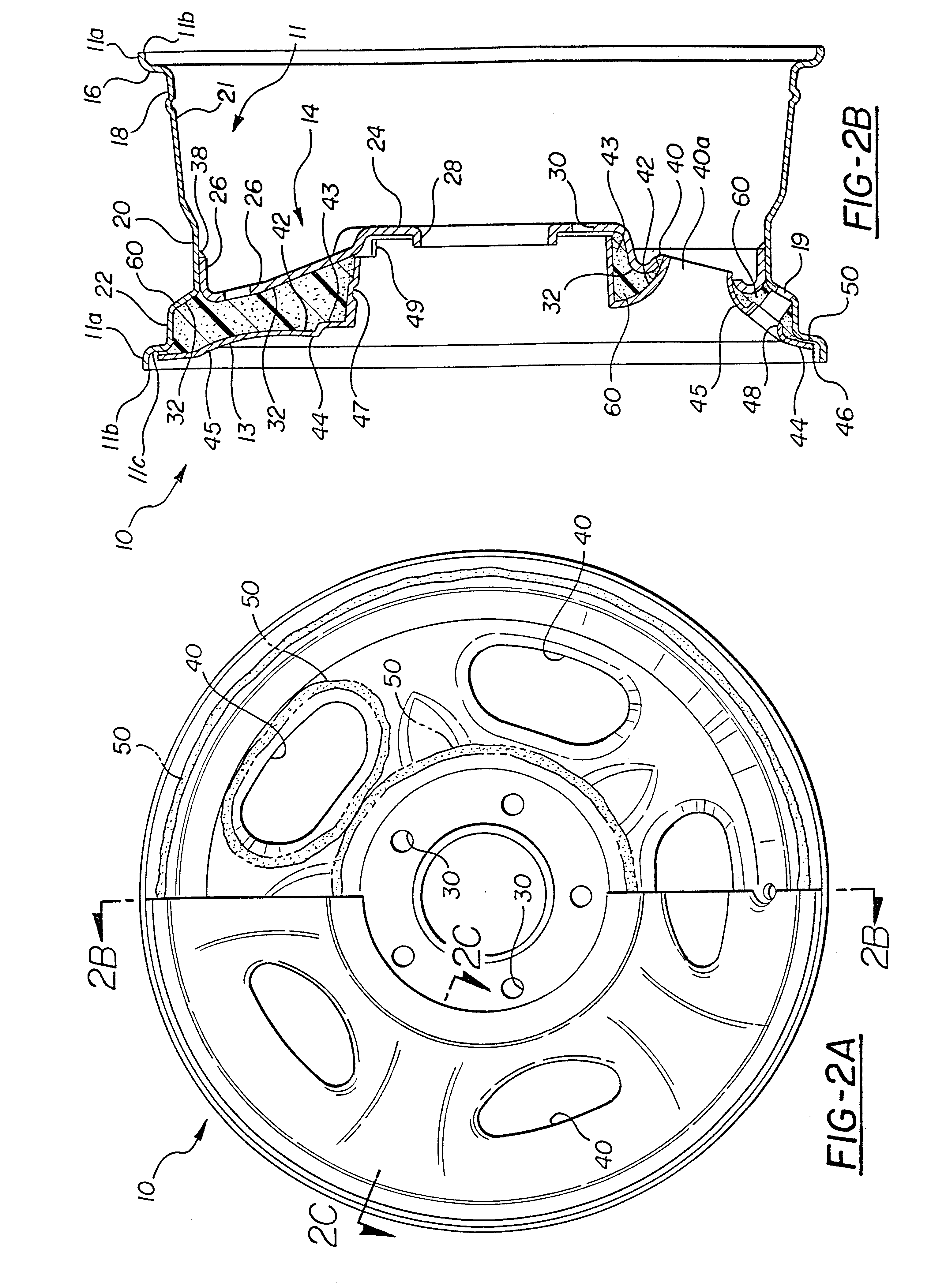
The overlay is configured to have variations in contours in a direction transverse to the axis of the wheel that exceed the variations in the rim and / or disc contour of the wheel, which variations would be extremely difficult and expensive, if not impossible, to stamp or draw in the disc of the wheel.
However, any excess polyurethane foam formed around the bolt holes or at the periphery of the assembly surrounding the axle hub will squeeze out if appropriate sealing provisions are not made.
Further problems with urethane formed wheels surfaced in use.
These wheels were very heavy due to the high density of the foam and variation in localized density during the manufacturing phase resulted in severe wheel imbalances.
Larger openings, such as turbine openings, would not be possible using the Derleth process without additional structure to seal the openings to prevent the foaming material from escaping.
A drawback of the process according to Derleth is that excess foam mixture is required to ensure that the cavity between the cover and the wheel is completely filled after the material vents out through the bolt openings.
For example, if the wheel hub was left unsealed it would provide a path for some of the foam to escape, and the security of the cover could be jeopardized.
Further, all of the excess foam must be manually removed, which adds significant cost to the process.
A further disadvantage of the process of Derleth is that the polyurethane foam adhesive completely breaks down at high temperatures, particularly in the immediate region of the wheel hub where temperatures tend to be much higher than in the remainder of the wheel.
The method according to Derleth has been known since the early 1970's and due to its many disadvantages has yet to realize practical applications and commercial success.
The process cannot accommodate the application temperature requirements, the need for lighter weight components, and degradation of the urethane adhesive over time, as well as the need for turbine openings in the outboard face of the wheel.
Further, the process is extremely costly due to the labor intensive trimming operations, difficult process control, environmental, health and safety concerns.
The teachings of Beam, U.S. Pat. Nos. 5,368,370 and 5,461,779, of a full surface curable adhesive are prohibitively expensive and wasteful since there is no need for a full surface uniform layer of adhesive to hold the overlay to the wheel.
Further, a full surface uniform layer of curable adhesive also detrimentally affects the balancing considerations of the wheel and overlay assembly.
The requirement of an intermediate positive fixing element not only adds costs to the overlay but requires careful handling and special packaging, all adding to the overall cost of the assembly.
Either too much foam will be injected into the cavity and foam will flash out through any opening between the wheel and the overlay, as seen in the Derleth process, requiring trimming, or not enough foam will be injected into the cavity resulting in voids and inadequate cover retention.
Further, it has been found that the use of a UV cure urethane adhesive / sealant significantly reduces cure time to a few minutes.
It is contemplated that other structural elements may be used to center the wheel as well as to accommodate tolerance variations that may result in unacceptable user-perceived aesthetic conditions.

Method used


Image

  • Vehicle wheel construction process
  • Vehicle wheel construction process
  • Vehicle wheel construction process

Examples


Embodiment Construction

Generally the process of assembly, 100, of the present invention, shown in flow chart form in FIG. 3A and FIG. 3B, involves fixturing an overlay, 102, applying an adhesive, locating a wheel to the overlay, 110 and 120, thereby defining a cavity or voids 43 therebetween, preheating the overlay / wheel assembly 130, and filling the overlay / wheel assembly with a foam adhesive 140, 150. There are various optional steps and alternatives that will be discussed in detail throughout this assembly process.

Referring generally to FIGS. 2A through 3B, while the preferred process 100 teaches the use of an adhesive sealant 50 shown in FIG. 2C applied to the overlay 13 prior to locating the overlay 13 to the wheel 10 to serve the stated purposes, the process may be practiced without the use of the adhesive sealant 50 disclosed in the preferred embodiment or, alternatively, adhesive sealant may be used on the respective mating surfaces of the wheel 10 and overlay 13 around the turbine openings. It is...


PUM

PropertyMeasurementUnit
temperatureaaaaaaaaaa
temperaturesaaaaaaaaaa

Abstract

An improved process for permanently attaching an overlay to a wheel disc, wherein the overlay is aligned and spaced apart from the wheel disc. A mold is created by a combination of the overlay, wheel disc and localized nests that engage at predetermined times during foam filling to close the mold. The mold is adequately sealed so that there is no foam leakage as the foam expands to fill the mold and, therefore, no final trimming of excess foam is required. The improved process is capable of accommodating a wheel having turbine openings therein.

Description

1. Field of the InventionThe present invention relates to composite wheel assemblies for vehicles having an overlay permanently attached to a wheel disc with a combination of adhesives and, particularly, to an improved apparatus and process for permanently attaching an ornamental overlay to the wheel using nests to locate and support the overlay to the wheel creating a mold into which foam can be injected.2. Description of the Prior ArtDecorative overlays are widely used to enhance the aesthetic appearance of automotive wheels. Overlays are not only employed to improve the appearance of unadorned standard steel wheels, but are also used with cast aluminum wheels, that are known to be expensive and difficult to plate with chromium. Numerous structural combinations of overlays with chrome-plated outboard surfaces have attracted great interest from vehicle manufacturers, because they are lightweight, aesthetically pleasing and offer designers complete flexibility with regard to the aes...

Claims


Application Information

Patent Timeline
Patent Type & Authority Patents(United States)
IPC IPC(8): B60B7/00
CPCB29C44/1233B60B7/02B60B31/06B60B7/063B60B7/065B60B7/18B60B7/06B29L2031/32
Inventor CHASE, LEE A.NEEB, DOUGLAS LOUISSHEA, ROBERT E.
Owner LACKS INDUSTRIES INC
Why Eureka
Try Eureka