Conditioner circuit for magnetic field sensor

Inactive Publication Date: 2002-02-12
FAST TECH
View PDF14 Cites 42 Cited by
  • Summary
  • Abstract
  • Description
  • Claims
  • Application Information

AI Technical Summary

Problems solved by technology

The points of saturation for the opposite drive polarities in the coil become unbalanced due to the presence of an external field and it is this unbalance that is ...

Method used


Image

  • Conditioner circuit for magnetic field sensor
  • Conditioner circuit for magnetic field sensor
  • Conditioner circuit for magnetic field sensor

Examples


Embodiment Construction

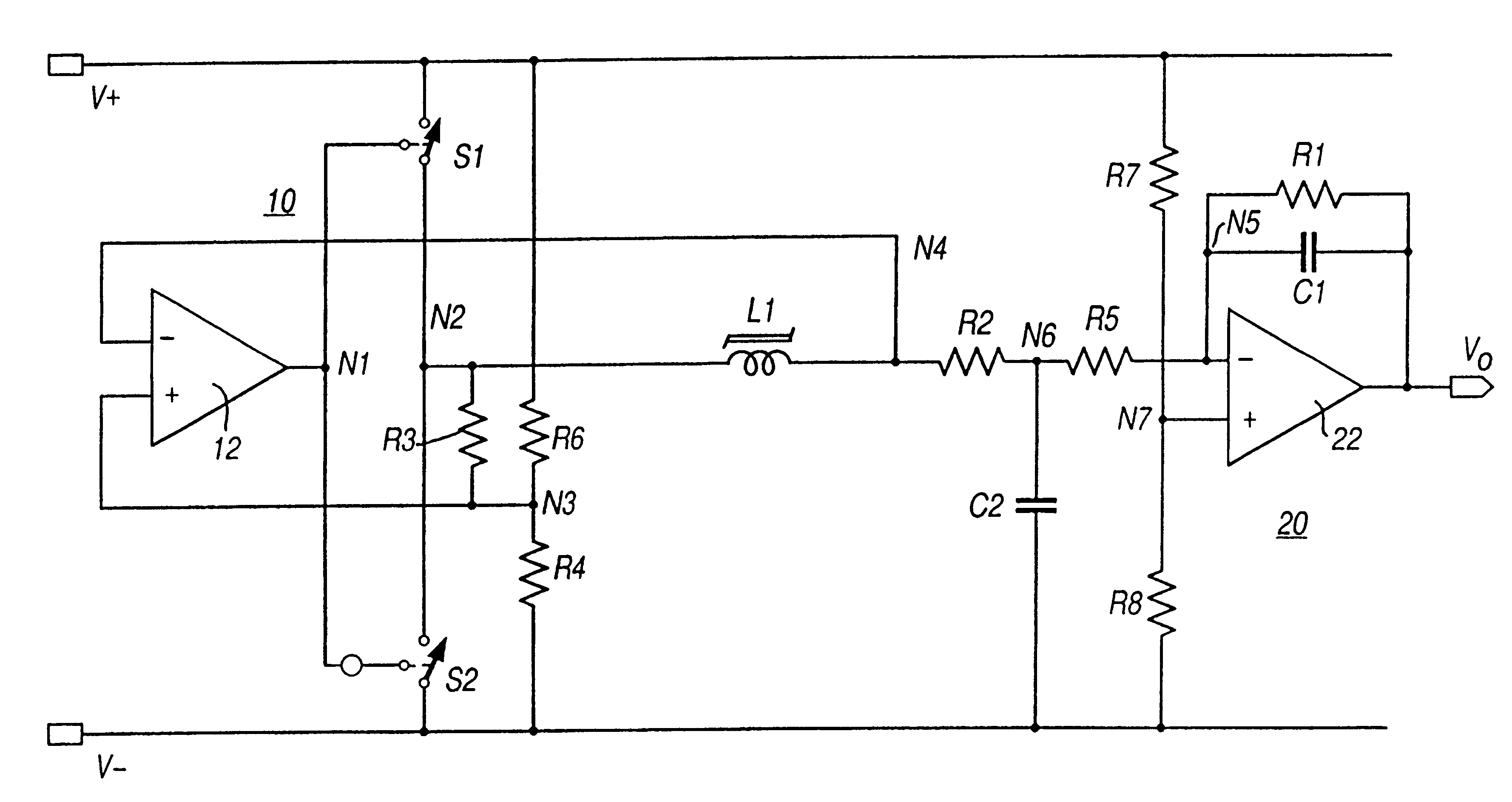
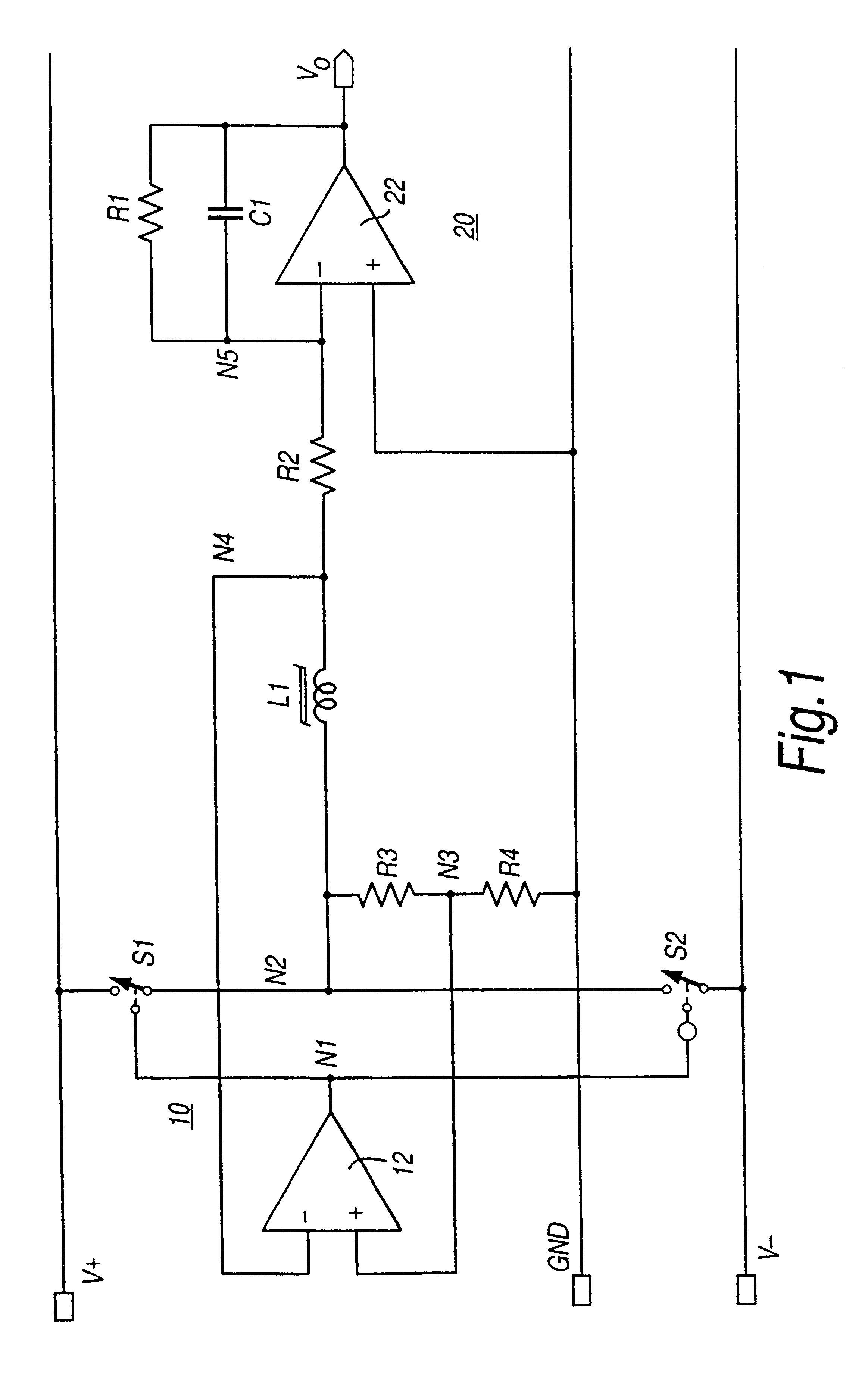
Referring to FIG. 1, the saturable inductor for sensing the magnetic field is denoted L1. Although a single coil is shown, the torque transducer may use a number of coils. Arrangements having two or four coils have been proposed. As already explained the transducer construction itself is not part of this invention. If multiple coils are used, then they may be series connected so that the coil L1 represents the series of coils in such a case. Series connection of multiple coils is not essential.

The circuit of FIG. 1 comprises two linked portions, a driver circuit 10 for coil L1 in which the coil is an integral part of a switched oscillator, and a current measuring circuit 20 responsive to the unbalance current in the coil due to the applied external magnetic field sensed by the transducer. The driver and current measuring circuits are connected between positive and negative supply rails V+ and V- assumed of equal magnitude with respect to ground GND.

In the driver circuit 10, a compar...


PUM


Abstract

A circuit for sensing a magnetic field has at least one saturable coil (L1). The circuit includes switches (S1, S2) controlled by a comparator (12) to drive the coil (L1) to saturation by alternating polarities of current. In the absence of an external magnetic field the currents are balanced. An applied external magnetic field causes an unbalance in the coil (L1) in reaching saturation. An unbalance current is applied through a sensing resistor (R2) to an integrator (20) to develop an output voltage (Vo) as a measure of the applied magnetic field. The switches (S1, S2) are implemented by transistor switches. Dual (FIG. 1) and single (FIG. 2) supply rail circuits are disclosed. The circuit finds particular application in torque transducers using magnetoelastic elements.

Description

This invention relates to a circuit for use with a sensor responsive to magnetic fields, and has particular, though not exclusive application, to what is known as a torque sensor.Magnetoelastic torque sensors are known in the art. They are used to sense a magnetic field emanated by a magnetoelastic element mounted to a shaft due to the torque resulting from rotation or attempted rotation of a shaft. The rotation of any shaft from one end to drive a load at the other end generates torque in the shaft due to differential angular displacement (which may be very small) between the point at which drive is applied and the point at which the load is driven. If magnetoelastic means generating a magnetic field is associated with a shaft the field becomes distorted by the torque in the shaft and such distortion can be sensed as a measure of torque.BACKGROUND TO THE INVENTIONIt has further been proposed to sense the distortion of the magnetic field away from its quiescent (non-torque) state by...

Claims


Application Information

Patent Timeline
IPC IPC(8): G01L3/10G01R33/04
CPCG01L3/105G01L3/102
Inventor MAY, LUTZ AXELBROKAW, ADRIAN PAUL
Owner FAST TECH
Why Eureka
Try Eureka