Substrate treating apparatus and substrate treating method

a substrate and treating apparatus technology, applied in the direction of thin material processing, cleaning process and apparatus, cleaning using liquids, etc., can solve the problems of high possibility of cracking of the substrate, damage or breakage of the substrate, and difficulty in detachment, so as to prevent the tilting and adhesion of adjacent substrates, prevent the damage of the substrate, and generate the

Inactive Publication Date: 2002-03-05
DAINIPPON SCREEN MTG CO LTD
View PDF3 Cites 28 Cited by
  • Summary
  • Abstract
  • Description
  • Claims
  • Application Information

AI Technical Summary

Benefits of technology

It is another object of the invention to provide a substrate treating apparatus and a substrate treating method capable of preventing tilting and adhesion of adjacent substrates during a h...

Problems solved by technology

Accordingly, it may be difficult to detach the adjacent substrates 53 in contact, and a forcible detachment of the substrates 53 may result in a damage or a breakage of the substrate(s) 53.
The last problem is significant particularly in the case where the substrate group is held ...

Method used


Image

  • Substrate treating apparatus and substrate treating method
  • Substrate treating apparatus and substrate treating method
  • Substrate treating apparatus and substrate treating method

Examples


first embodiment

[First Embodiment]

A first embodiment of this invention is described with reference to FIGS. 5 to 7.

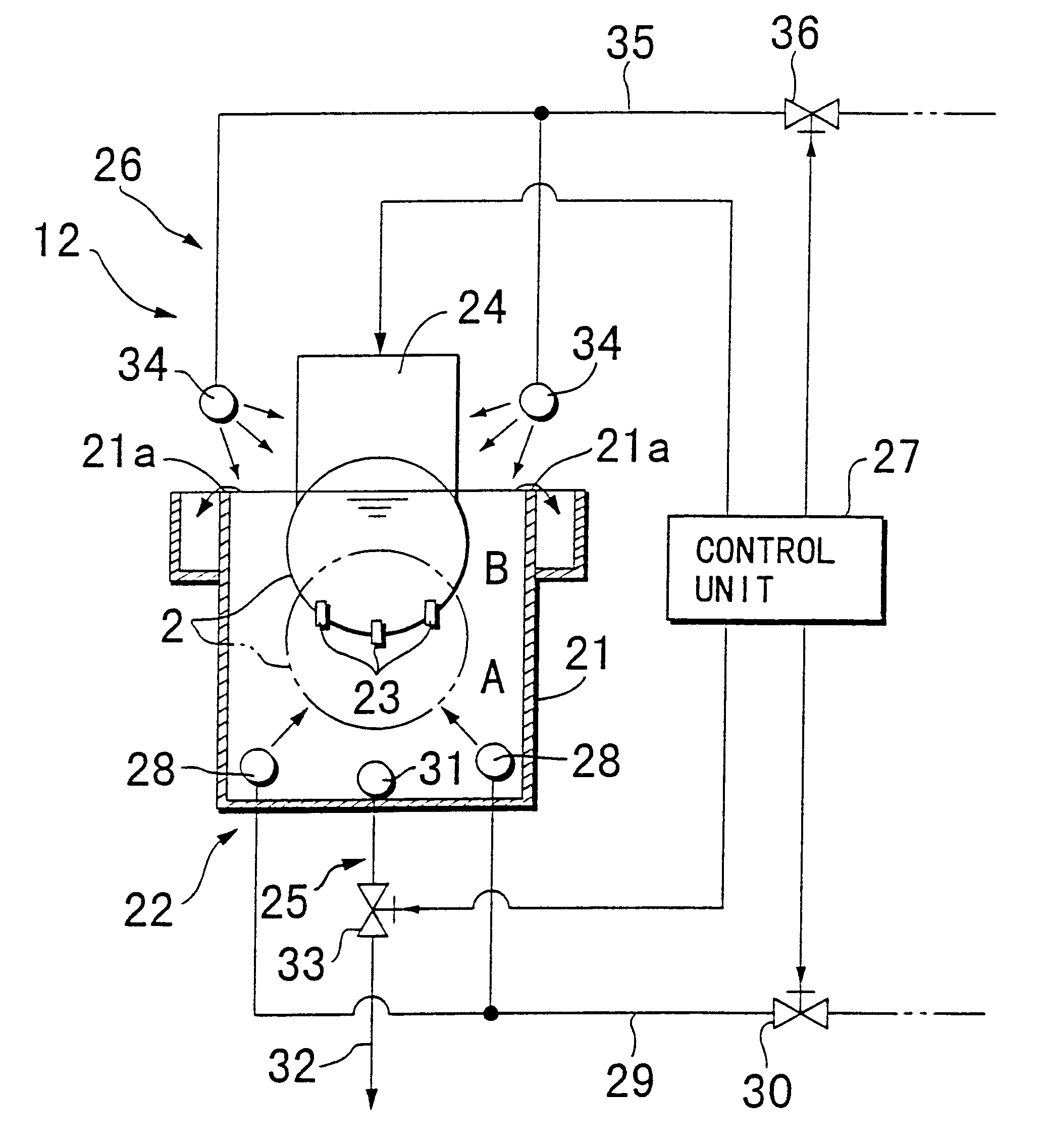
FIG. 5 is a diagram showing a schematic construction of the mechanical rinsing section as a first embodiment. In FIG. 5, the mechanical rinsing section 12 comprises a water bath 21, a de-ionized water supply unit 22, a lifter 24, a drainage system 25, a shower unit 26, and a control unit 27 (controller 27). The water bath 21 is a treating bath opened upward to allow the substrate group 2 to be immersed from upward in de-ionized water (or treating liquid) filled therein. The water supply unit 22 supplies de-ionized water to the water bath 21 to overflow the water. The lifter 24 is an elevating mechanism adapted for immersing the substrate group 2 in an upright posture in the de-ionized water in the water bath 21. The drainage system 25 drains a processed liquid from the water bath 21 (in this embodiment, a solution mixed with de-ionized water and phosphoric acid) at a high speed. The pr...

second embodiment

[Second Embodiment]

Next, a second embodiment of this invention is described with reference to FIGS. 8 to 10.

FIG. 8 is a diagram showing a schematic construction of the mechanical rinsing section embodying the substrate treating apparatus of this invention as a second embodiment. The second embodiment is similar to the first embodiment except the construction and the control operation of draining the processed liquid from the water bath 21. Specifically, the construction of a water bath 21, a de-ionized water supply unit 22, a lifter 24, and a shower unit 26 of the second embodiment is the same as those of the first embodiment, and accordingly, description thereof is omitted herein, and the elements in this embodiment that are identical to those in the first embodiment are denoted at the same reference numerals.

A mechanical rinsing section 12 of the second embodiment is provided with a first drainage unit 25a and a second drainage unit 25b for draining the processed liquid from the w...

third embodiment

[Third Embodiment]

A third embodiment of this invention is described with reference to FIG. 11. In the second embodiment, the first drainage unit 25a and the second drainage unit 25b are selectively controlled to change the drainage manner. In the third embodiment, a variable speed setter capable of altering the drainage speed stepwise is used. To simplify the description of the third embodiment, exemplified is a dual speed setter capable of altering the drainage speed at two stages. Similar to the second embodiment, elements in this embodiment that are identical to those in the first embodiment in the aspect of operation and effect are denoted at the same reference numerals. Further, it should be noted that the operation before and after the mechanical rinsing operation in this embodiment is the same as the first embodiment, and accordingly, description thereof is omitted herein.

FIG. 11 is a schematic cross sectional diagram showing part of the mechanical rinsing section as the thir...


PUM


Abstract

A control unit controls a lifter to raise at least part of each of a group of substrates above the liquid level of a treating liquid in a treating bath. Thereafter, a valve is opened to drain the treating liquid from the treating bath at a high speed. As a result, a physical force to tilt and adhere an upper portion of the adjacent substrates accompanied by lowering of the liquid level of the treating liquid due to the high speed drainage acts upon a lower portion of the substrates near the lowered liquid level of the treating liquid, thereby reducing the physical force exerted on the substrates. This arrangement, even if a holding interval between the substrates is narrowed at a half of a normal pitch, eliminates a contact of the adjacent substrates and prevents damage of the substrates due to the contact without providing an additional member such as a substrate support guide in the treating bath.

Description

1. Field of the InventionThis invention relates to a substrate treating apparatus and a substrate treating method in which a substrate having a very small thickness such as a semiconductor substrate and a glass substrate for use in a liquid crystal display panel (hereinafter, merely referred to as a "substrate") is immersed in a treating liquid such as a chemical liquid and de-ionized water (or refined water) filled in a treating bath to apply a certain treatment onto the substrate.2. Description of the Background ArtThere have conventionally been conducted various surface treatments in which a substrate is immersed in a treating liquid in a process of producing a substrate for use in a precision electronic device. One of known substrate treating apparatus comprises a chemical bath filled with a chemical liquid such as etchant and photoresist film peeling liquid and a water bath filled with de-ionized water (or refined water).More specifically, after a substrate is immersed in a che...

Claims


Application Information

Patent Timeline
IPC IPC(8): B08B3/10H01L21/00
CPCH01L21/67051B08B3/102H01L21/67057
Inventor ARAKI, HIROYUKIARAI, KENICHIROYABUTA, MASAAKI
Owner DAINIPPON SCREEN MTG CO LTD
Why Eureka
Try Eureka