Method of manufacturing a backrest structure for a vehicle seat and backrest structure obtained by this method

a backrest structure and vehicle seat technology, applied in the field of manufacturing a backrest structure for a vehicle seat and a backrest structure obtained by this method, can solve the problems of relative cost and complicating the manufacturing process of the backrest structure, and achieve the effect of reducing the cost of manufacturing backrest structures, no more complex or expensive, and easy absorption of manufacturing tolerances

Inactive Publication Date: 2002-03-05
BERTRAND FAURE EQUIP SA (FR)
View PDF11 Cites 62 Cited by
  • Summary
  • Abstract
  • Description
  • Claims
  • Application Information

AI Technical Summary

Benefits of technology

Furthermore, the method proposed by the invention will easily absorb the manufacturing tolerances on the length of the vertical uprights of the backrest structure.
Furthermore, the same hydroforming equipment may be used to make backrest structures of the same external shape but incorporating material of differing thicknesses, which will reduce the cost of manufacturing backrest structures since a same backrest structure (for example, a backrest for "3 seater" vehicles and for "2 seater" vehicles in which the boot is not totally separated from the area reserved for the rear passengers).
Finally, the operation whereby orifices are punched into the crosspieces is a commonplace operation in the hydroforming process, which will be made no more complex or expensive as a result.

Problems solved by technology

This method is quite satisfactory but has a disadvantage in that said other lateral upright can only be joined to the bottom and top crosspieces by welding, which is relatively expensive.
In addition, the weld seams are always critical points of the backrest structure and have to be controlled very carefully, thereby complicating the process of manufacturing the backrest structure.
These disadvantages are major under all circumstances but become critical if the backrest structure is made from aluminium or an aluminium-based alloy insofar as welding these materials is a particularly delicate operation.

Method used


Image

  • Method of manufacturing a backrest structure for a vehicle seat and backrest structure obtained by this method
  • Method of manufacturing a backrest structure for a vehicle seat and backrest structure obtained by this method
  • Method of manufacturing a backrest structure for a vehicle seat and backrest structure obtained by this method

Examples


Embodiment Construction

The same references are used in the different drawings to denote the same or similar components.

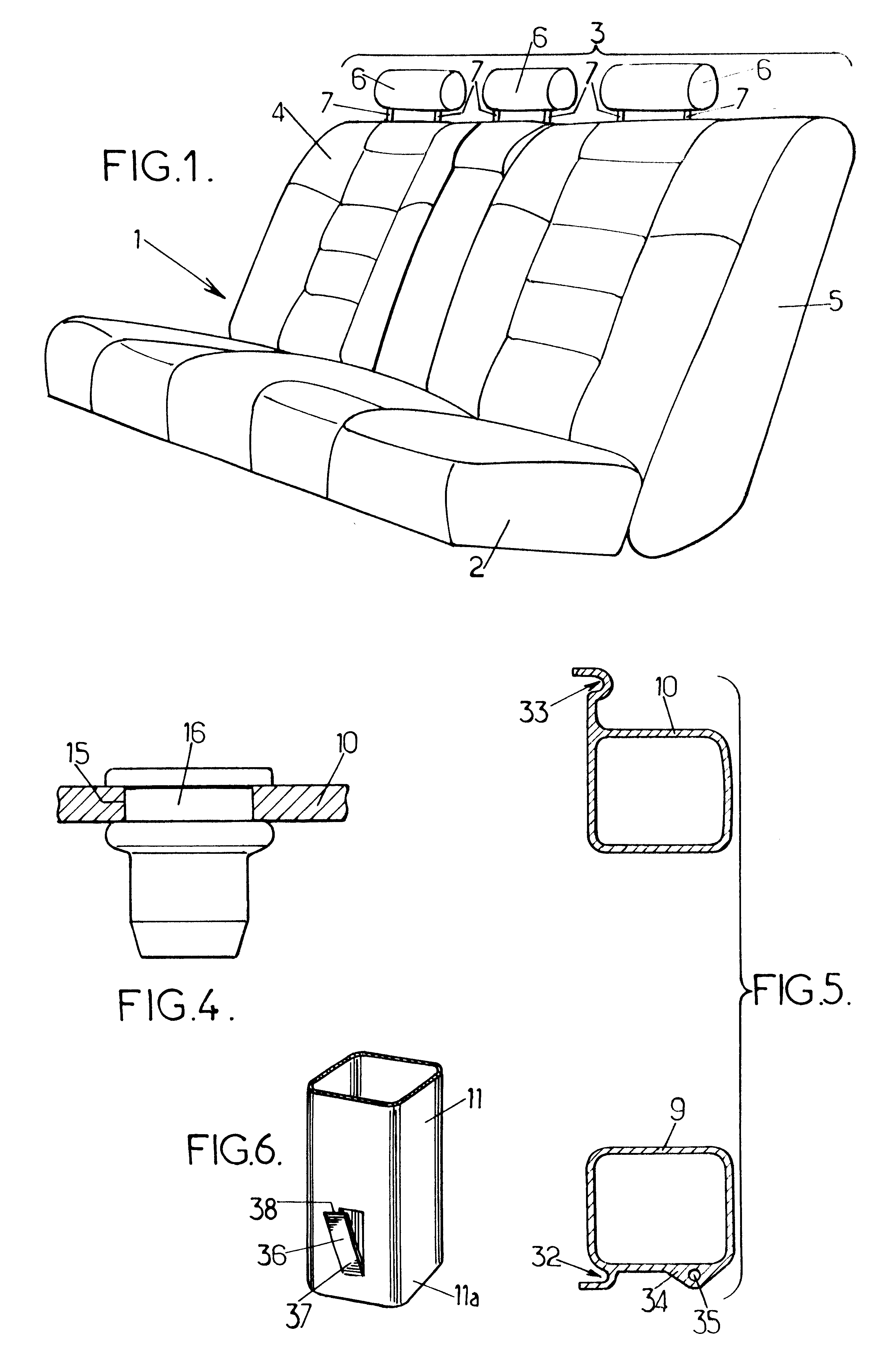
FIG. 1 illustrates a seat for a motor vehicle 1, in this case a rear seat, comprising a seat part 2 and a backrest 3.

In the specific example illustrated here, the backrest 3 comprises two parts 4, 5, which form approximately 1 / 3 and 2 / 3 of the width of the backrest 3 respectively and which can be folded down forwards independently of one another. The part 4 of the backrest forms a side place for a single passenger whilst the part of the backrest forms two adjacent places, namely a side place and a centre place.

Each of the three places in the seat 1 is provided with a headrest 6, borne by two vertical metal pins 7 mounted on the rigid structure of the backrest.

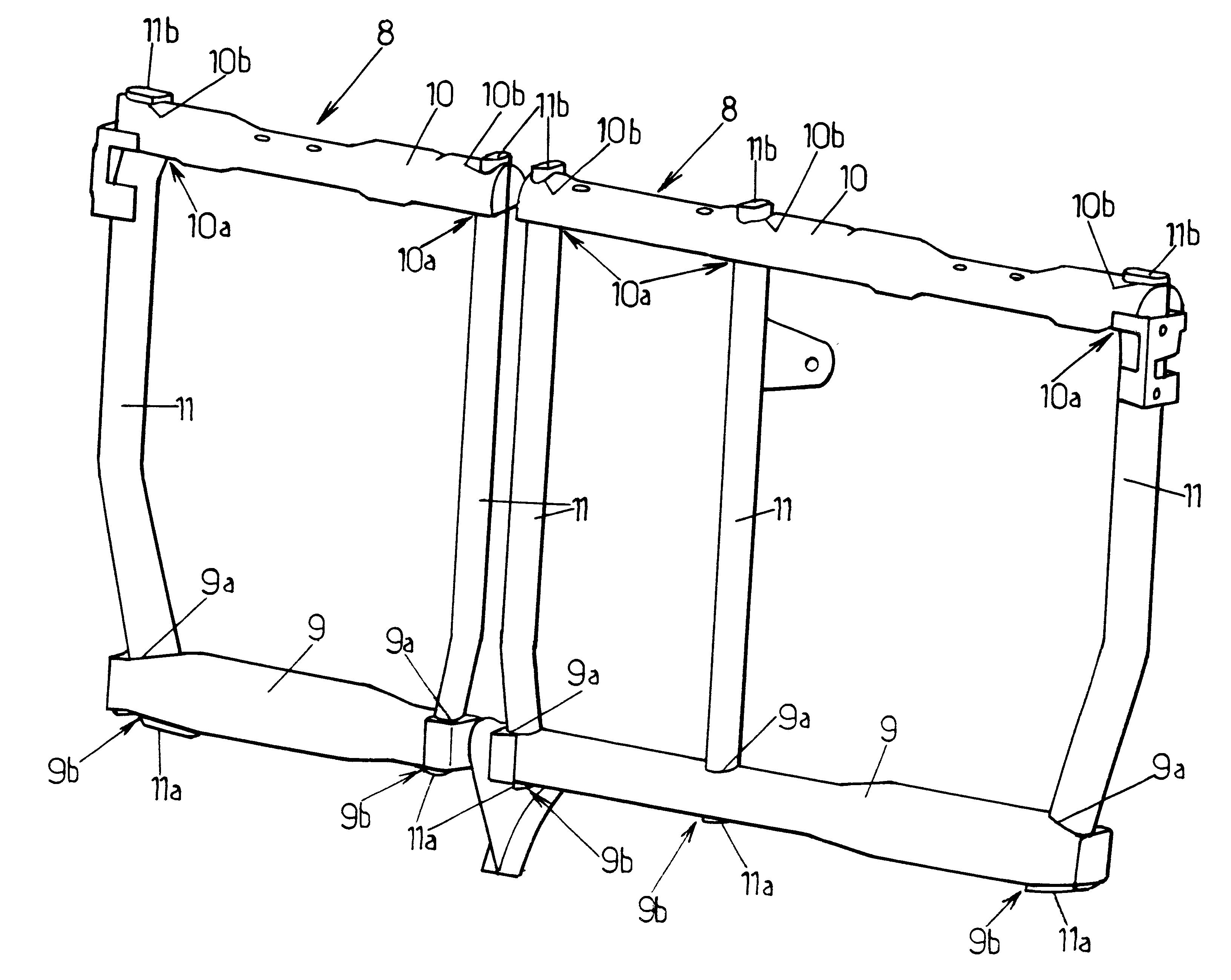
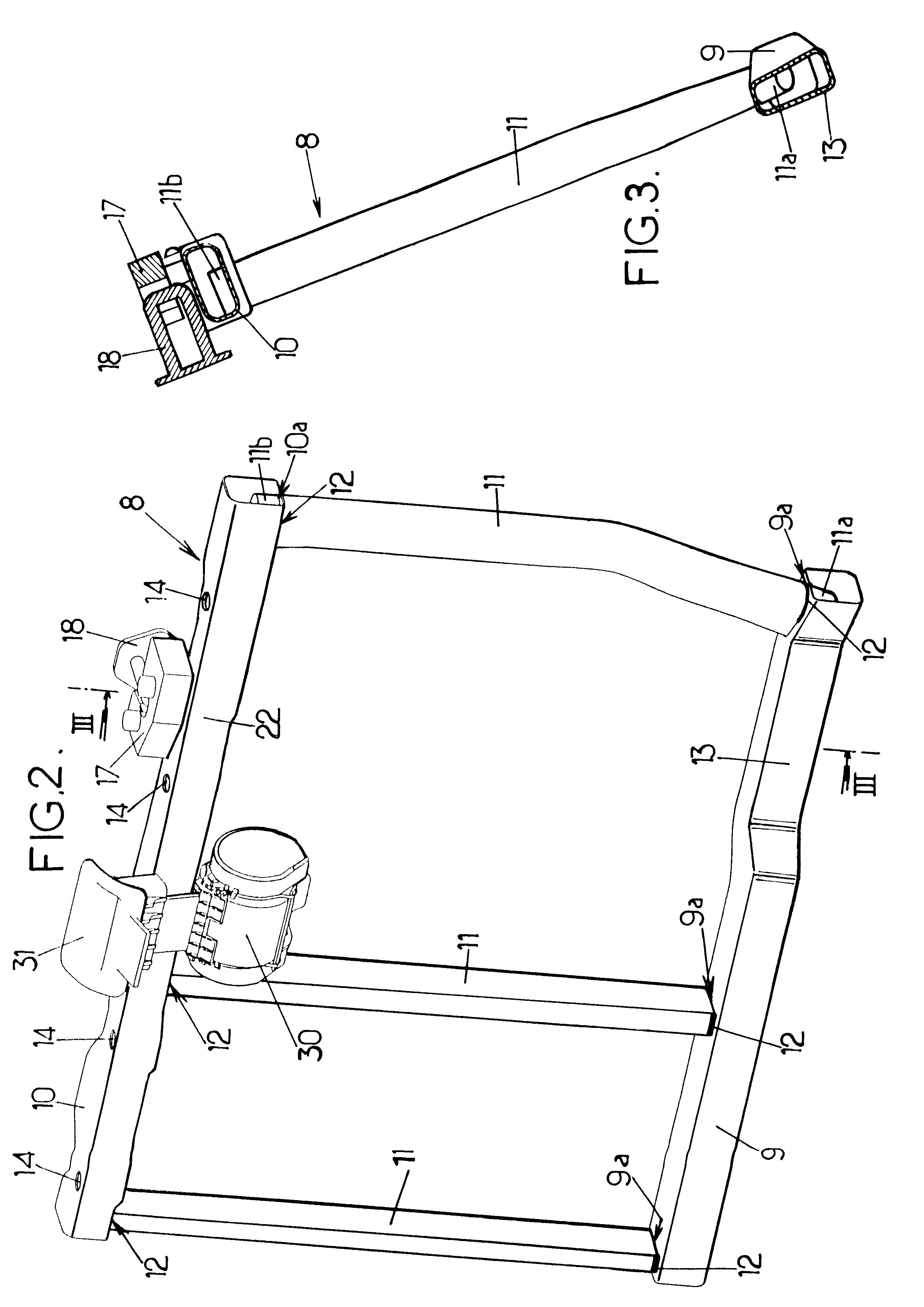
As illustrated in FIGS. 2 and 3, the rigid metal frame 8 of the part 5 of the backrest comprises:

a bottom tubular crosspiece 9 which extends horizontally,

a top tubular crosspiece 10, which also extends horizontally,

and three substant...


PUM

PropertyMeasurementUnit
interior volumeaaaaaaaaaa
volumeaaaaaaaaaa
mechanical strengthaaaaaaaaaa

Abstract

A backrest structure for a vehicle seat comprises two hydroformed, tubular, horizontal crosspieces and vertical uprights engaged without any clearance in orifices punched into these crosspieces during hydroforming.

Description

The present invention relates to methods of manufacturing backrest structures of seats for vehicles and the backrest structures produced by this method.More specifically, the invention relates to a method of manufacturing a backrest structure of a seat for a vehicle, this structure comprising:a tubular-shaped, rigid, bottom horizontal crosspiece delimiting a certain interior volume and comprising a bottom part and a top part,a tubular-shaped, rigid, top horizontal crosspiece delimiting a certain interior volume and comprising a bottom part and a top part,and at least first and second rigid, substantially vertical uprights, each of which extends between bottom and top ends joined respectively to the bottom and top crosspieces,said method comprising at least one step in which the bottom and top crosspieces are shaped by hydroforming.A method of this type is described in document FR-A2 753 935, for example, whereby one of the lateral uprights of the structure is made from a single piec...

Claims


Application Information

Patent Timeline
Patent Type & Authority Patents(United States)
IPC IPC(8): B60N2/68A47C7/40
CPCB60N2/682Y10T29/49805Y10T29/49622B60N2205/35B60N2/68
Inventor HAYOTTE, SEBASTIEN
Owner BERTRAND FAURE EQUIP SA (FR)
Why Eureka
Try Eureka