
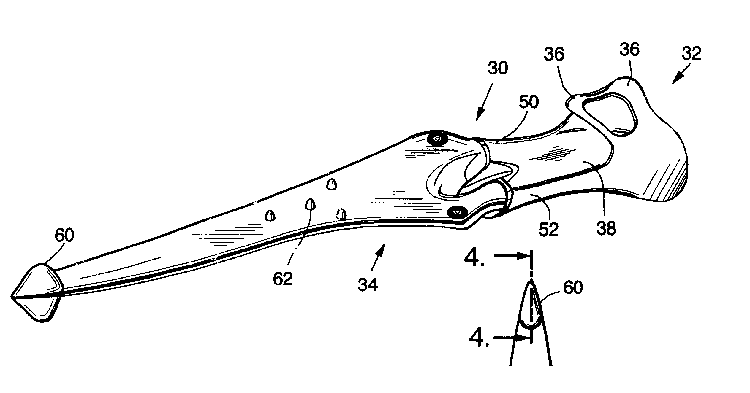
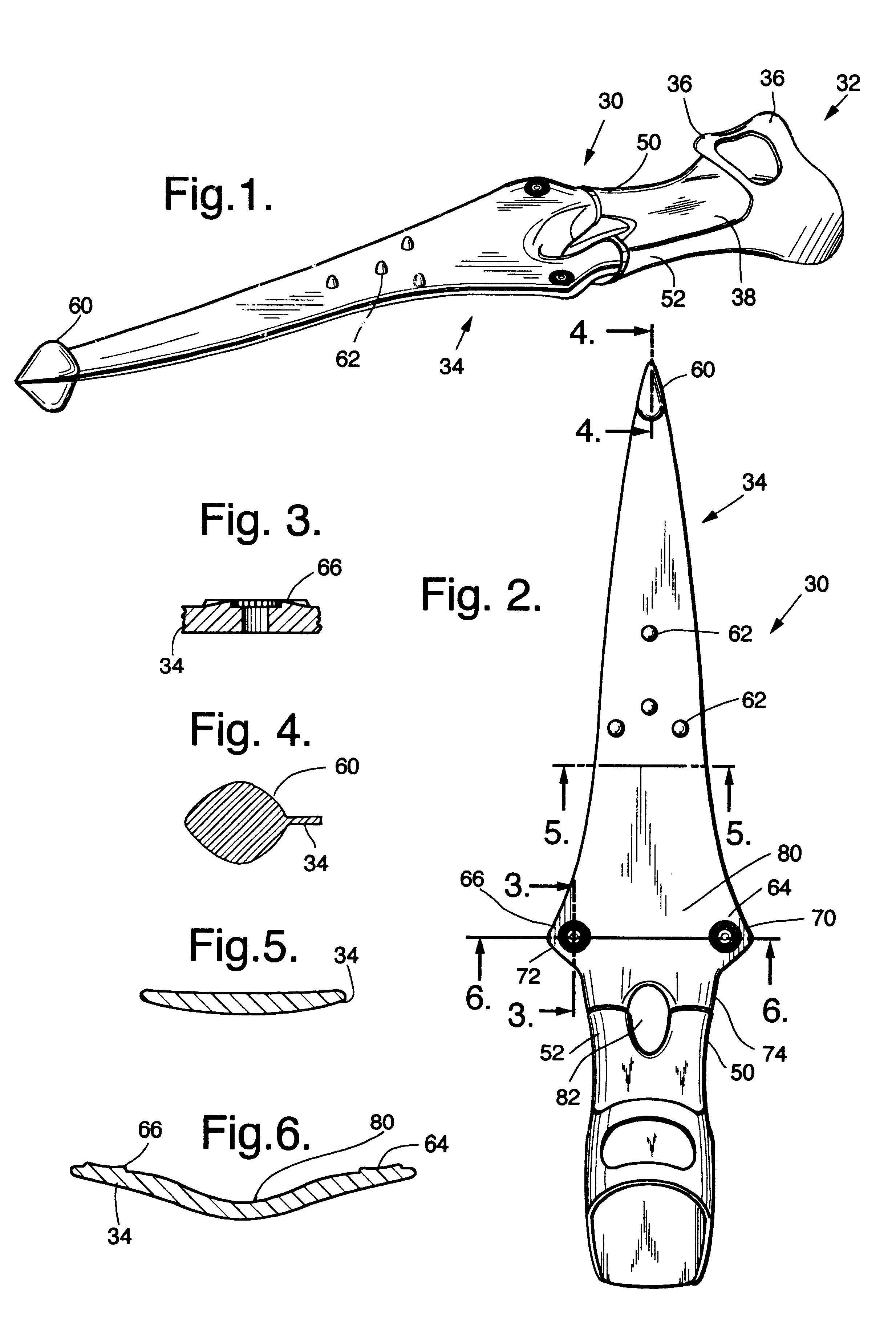
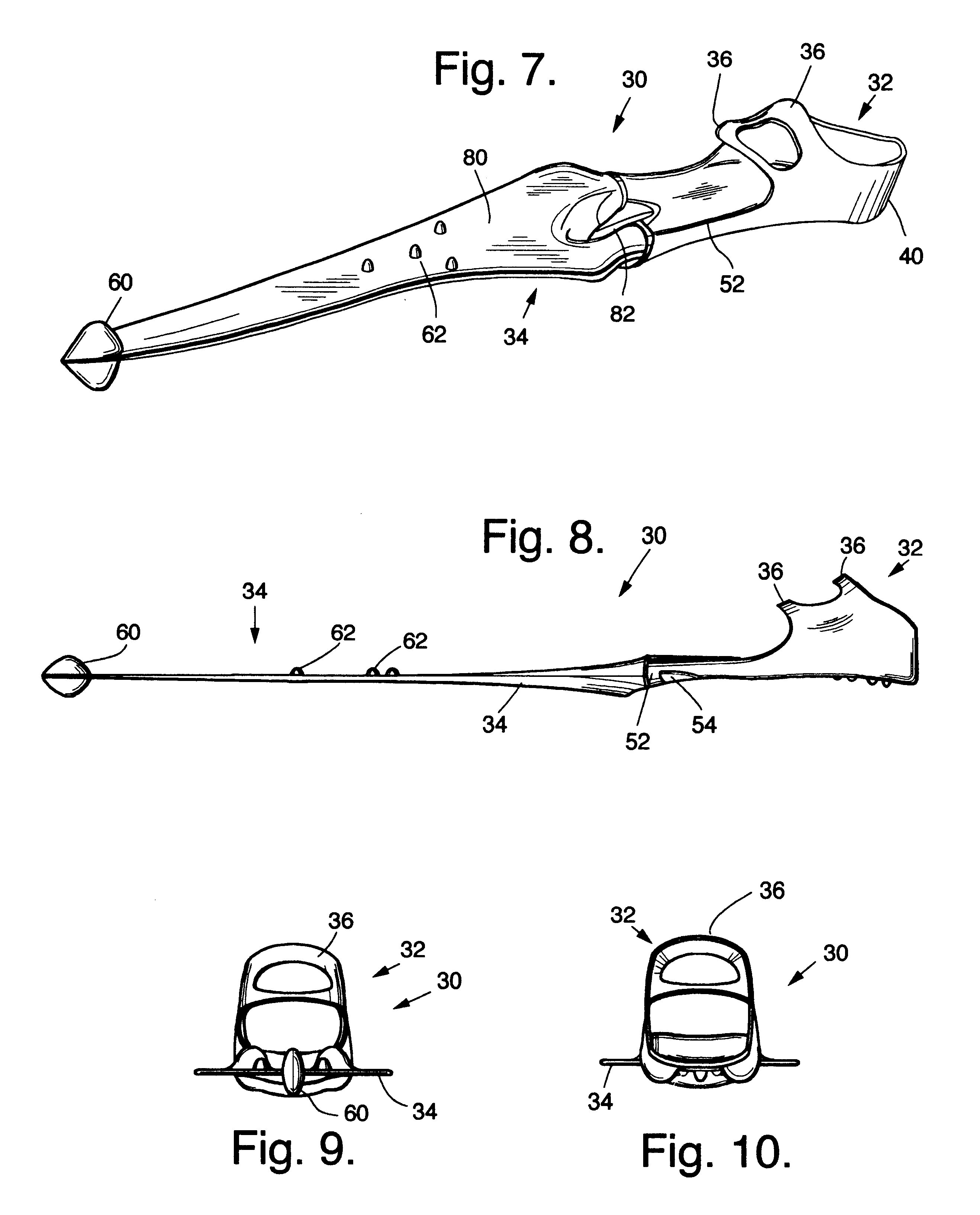
Spear-blade swim fin

a technology of swim fins and blades, applied in the field of swim fins, can solve the problems of not speed and unadjustable bladed swim fins, and achieve the effect of reducing dead areas and beneficial vortices

Inactive Publication Date: 2002-03-12
EVANS ROBERT B
View PDF23 Cites 4 Cited by
  • Summary
  • Abstract
  • Description
  • Claims
  • Application Information

AI Technical Summary

Benefits of technology

It is yet another object of the present invention to provide a spear-bladed swim fin that incorporates speed pods or the like to reduce dead areas, provide a counterweight, or create beneficial vortices.
It is yet another object of the present invention to provide a spear-bladed swim fin that may incorporate winglets or the like to control water flow over the fin surface.

Problems solved by technology

Fish with truncate or rounded caudal fins are usually strong swimmers, but are generally slow.
Apparently, such truncate or rounded caudal fins provide strength but not speed to the propulsive force of the fish while swimming due to the greater centralized surface area of such caudal fins.
Consequently, such swim fins provide strength, but generally not speed.
Additionally, such bladed swim fins are not adjustable, the lateral rails and the blade webbing not providing any adjustment with respect to the foot pocket.

Method used


Image

  • Spear-blade swim fin
  • Spear-blade swim fin
  • Spear-blade swim fin

Examples


embodiment 104

The wider nature of the wide spear blade embodiment 104 serves to provide more fin surface area against which the water may operate. Additional perimeter edge area is also present due to the outward extension of the flares 122, 124. Additionally, otherwise propulsive blade area is lost to the aperture 102 and its intrusion into the main spear blade portion 100 of the wide spear blade fin 104.

One advantage to the wide spear blade fin 104 is that by turning his ankles, the diver is able to provide thrust in sideways manners, thus allowing for greater attitudinal or dispositional control.

embodiment 30

As for the narrow spear blade embodiment 30, a speed pod 130 is present at the distal end 112 of the wide spear blade 100. The speed pod 130 operates in manner similar to that of the speed pod 60 shown with the narrow spear blade embodiment.

FIGS. 20A-C (as indicated by FIG. 20D) indicate the selectable adjustment of the swim fin blades 34, 100, depending upon their fixation to the foot pocket 32. Alternatively, and possibly in conjunction with the adjustable flexion of the swim fin blades 34, 100, the position where the flexing is determined may be reflected by the FIGS. 20A-C. For example, the swim fin marked A may generally correspond to the line 6--6 in FIG. 2. The swim fin marked B may correspond to the line 5--5 in FIG. 2. For the swim fin marked A (to the left in the FIG. 20 drawings), the swim fin blade 150 has been installed upon the foot pocket 32 in a significantly-flexed manner, either upward (B.sup.+) or downward (B.sup.-). In these high settings, more water is scooped o...


PUM


Abstract

Spear-bladed swim fins provide new means by which divers may propel themselves through the water. Spear-bladed swim fins generally provide a lower surface area to a higher perimeter edge length. By reducing the effective surface area of the swim fin, more propulsive force is delivered by the fin for each kick of the diver. Such dispersion of the diver's energy may be particularly advantageous where stationery swimming is required, as for underwater photography. Additionally, vortices generated during swim kicks may advantageously complement the operation of the swim fin. In the first embodiment, the spear blade is narrow. In a second embodiment, the spear blade is wider but has a larger channel through which water can flow to eliminate dead spots on the lee side of the fin. Fork extension stubs present with the foot pocket of the swim fin provide an adjustable means by which the flexing, bowing, and / or geometry of the swim fin blade may be adjusted according to the preferences and / or demands of the diver.

Description

CROSS-REFERENCES TO RELATED APPLICATIONSThis application is related to a contemporaneously-filed sister application by the same inventor entitled "Swim Fin Having Articulated Wing Members," the entirety of which is incorporated herein by this reference thereto.1. Field of the InventionThis invention relates to swim fins and more particularly swim fins of an advanced design that will allow canceling vortices and better propulsion.2. Description of the Related ArtWith the advancement of scuba diving and snorkeling, swim fins have likewise developed in order to propel the diver through the water. As with the swimming fins of fish, swim fins for human beings have certain dynamic characteristics that provide for different types of propulsion through the water.The analogy with fish and aquatic mammal fins is particularly apropos, as such fish fins serve to propel fish ranging in size from the smallest minnow to the largest whale. Additionally, if the rules of natural selection are assumed...

Claims


Application Information

Patent Timeline
Patent Type & Authority Patents(United States)
IPC IPC(8): A63B31/00A63B31/11
CPCA63B31/11
Inventor EVANS, ROBERT B.
Owner EVANS ROBERT B
Learn More