Band pass filter, antenna duplexer, and communication apparatus

a technology of band-pass filter and antenna duplexer, which is applied in the direction of coupling devices, electrical devices, waveguides, etc., can solve the problems of increasing the size of the overall dielectric block, difficult to design a specified band-pass characteristic and attenuation-pole frequency, and difficult to make a coupling between specified adjacent resonant lines of aligned plural resonant lines independently different from the coupling between the other resonant lines

Inactive Publication Date: 2002-03-12
MURATA MFG CO LTD
View PDF11 Cites 3 Cited by
  • Summary
  • Abstract
  • Description
  • Claims
  • Application Information

AI Technical Summary

Problems solved by technology

In such conventional dielectric filters, it is difficult to make a coupling between specified adjacent resonant lines of the aligned plural resonant lines independently different from the coupling between the other resonant lines.
Thus, there is a problem in that it is difficult to design a specified band-pass characteristic and attenuation-pole frequency.
Howev...

Method used


Image

  • Band pass filter, antenna duplexer, and communication apparatus
  • Band pass filter, antenna duplexer, and communication apparatus
  • Band pass filter, antenna duplexer, and communication apparatus

Examples


first embodiment

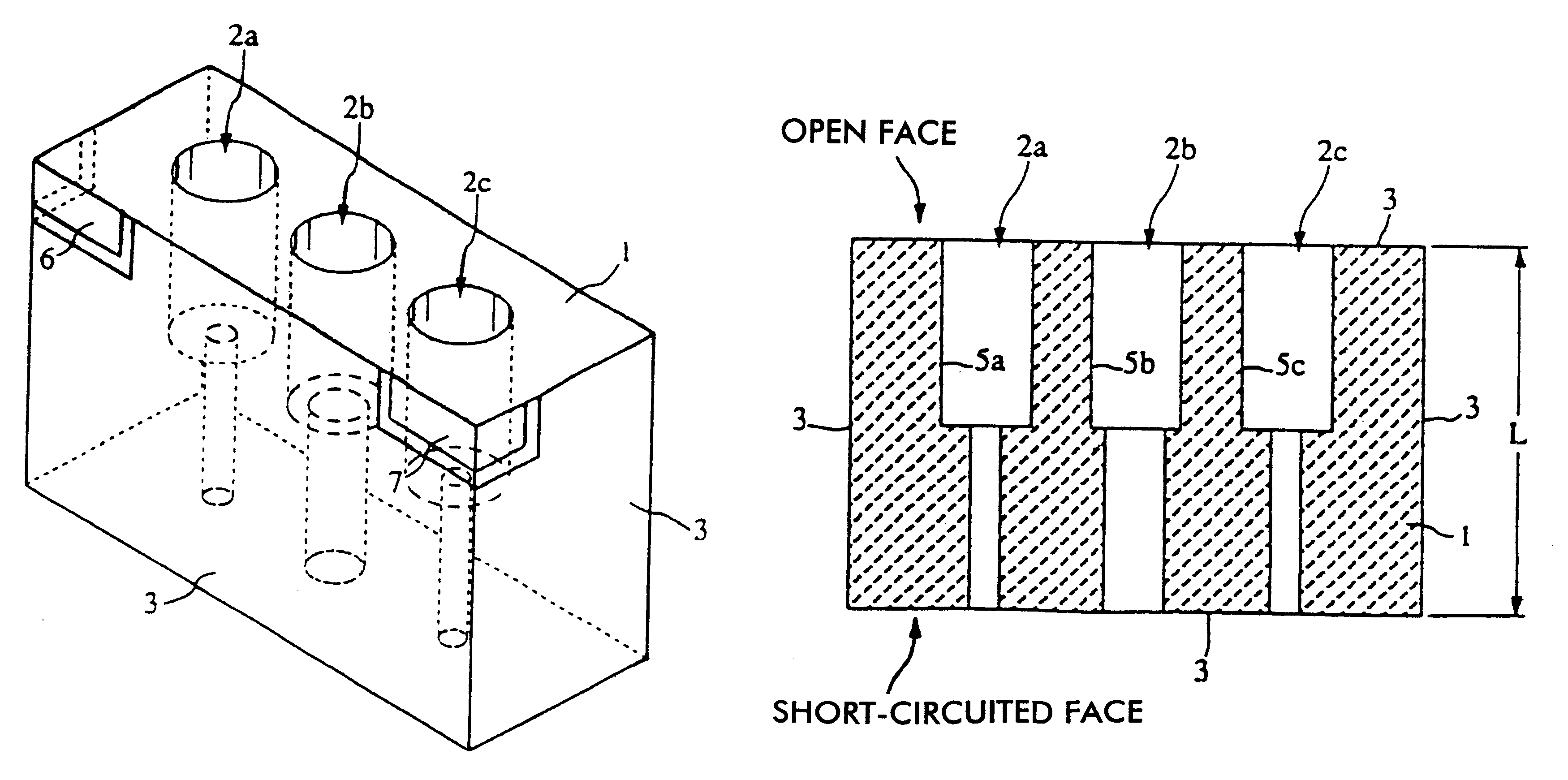
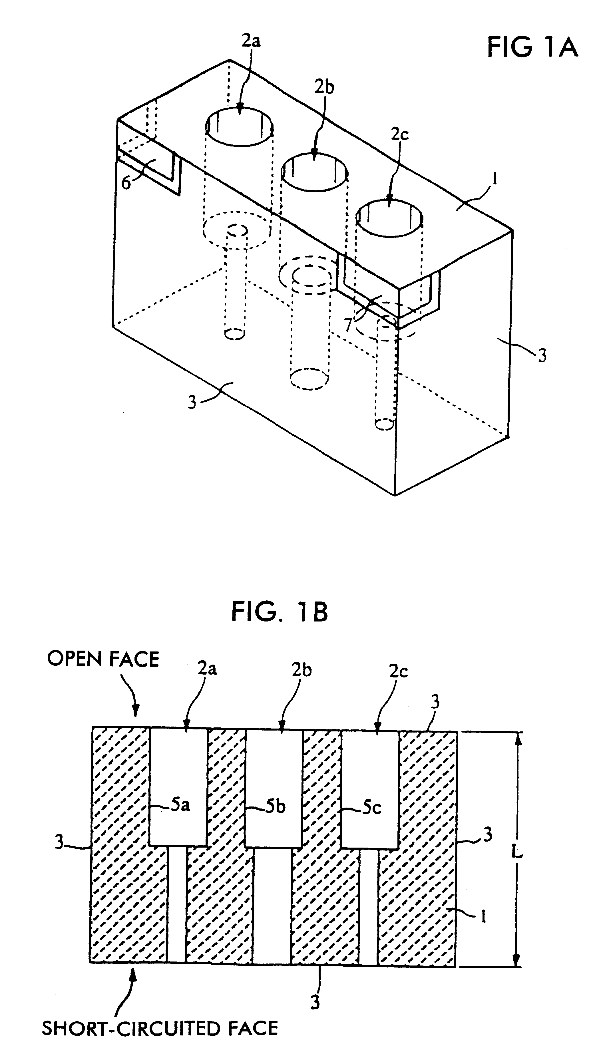
The structure of a band pass filter according to the present invention will be illustrated by referring to FIGS. 1A and 1B.

FIG. 1A is a perspective view of the band pass filter and FIG. 1B is a vertical-sectional view of the filter shown in FIG. 1A. In this figure, reference numeral 1 denotes a rectangular-parallelepiped dielectric block. Three resonant-line holes 2a, 2b, and 2c, which pass through from an end face of the dielectric block to the other opposing end face thereof, are aligned in such a manner that they are mutually in parallel. On the inner surfaces of the resonant-line holes 2a, 2b, and 2c, resonant lines 5a, 5b, and 5c are disposed. In addition, on the outer surface of the dielectric block 1, that is, on the five surfaces except one opening face of each of the resonant-line holes 2a, 2b, and 2c, an outer conductor 3 is disposed. The open face of the dielectric block 1, where no outer conductor is formed, is the open end of each of the resonant lines 5a, 5b, and 5c, a...

second embodiment

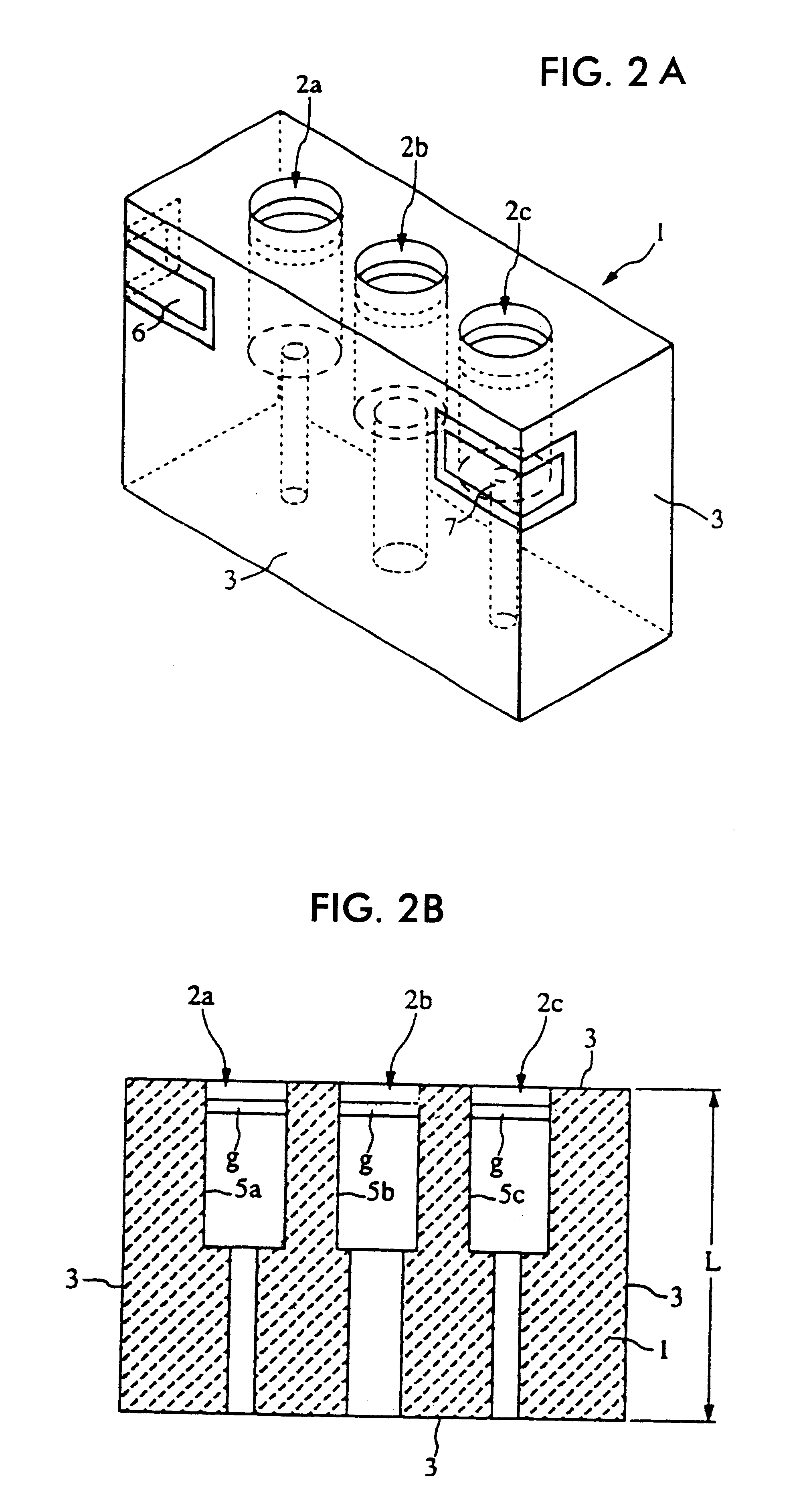
Next, the structure of a band pass filter will be illustrated by referring to FIGS. 2A and 2B.

The band pass filter is different from the band pass filter shown in FIGS. 1A and 1B in terms of a point that the open ends of the resonant lines are disposed inside the resonant-line holes. That is, in FIGS. 2A and 2B, reference numeral 1 denotes a substantially rectangular-parallelepiped dielectric block, in which three resonant-line holes 2a, 2b, and 2c passing through from one end face of the dielectric block 1 to the other opposing end face thereof are disposed in such a manner that they are mutually in parallel. An outer conductor 3 is disposed on the six outer surfaces of the dielectric block 1. On the inner surfaces of the resonant-line holes 2a, 2b, and 2c, resonant lines 5a, 5b, and 5c, which are opened at nonconductive portions g near one side openings, are disposed. The surfaces (short-circuited surfaces) opposing the open-end side surfaces are the short-circuited ends of the r...

third embodiment

Next, the structure of a band pass filter according to the present invention will be illustrated by referring to FIG. 3.

Although the first and second embodiments adopt the example of the band pass filter having a three-stage resonator, the band pass filter according to the third embodiment is constituted of a four-stage resonator. That is, four resonant-line holes 2d, 2e, 2f, and 2g passing through from one end face of the dielectric block 1 to the other opposing end face thereof are disposed in such a manner that they are mutually in parallel. One of the outer surfaces of the dielectric block 1 is an open face, and an outer conductor 3 is disposed on the other five surfaces thereof. Resonant lines are formed on the inner surfaces of the resonant-line holes 2d, 2e, 2f, and 2g. The surfaces (short-circuited surfaces) opposing the surfaces of the open-end sides are the short-circuited ends of the resonant lines. In addition, terminal electrodes indicated by reference numerals 6 and 7 ...


PUM


Abstract

There is provided a band pass filter comprising three or more resonant-line holes disposed in a dielectric block, a resonant line formed on each inner surface of the holes, and an outer conductor disposed on the outer surfaces of the dielectric block so that a dielectric filter is formed; wherein one end of the resonant line is a short-circuited end, and the other end thereof is an open end; the sectional area size of each of the resonant-line holes is changed at a certain point in the axial direction of the resonant-line hole; the sectional area size on the short-circuited-end side or open-end side of at least one of the plurality of resonant-line holes is made differently from those of the other resonant-line holes; and regarding the resonant-line holes symmetric with respect to a symmetry axis made at the center in a direction in which the plurality of resonant-line holes is aligned, the sectional area sizes of the short-circuited-end side or open-end side thereof are made the same so as to form coupling between adjacent resonant lines.

Description

1. Field of the InventionThe present invention relates to band pass filters, antenna duplexers used in high-frequency bands, and communication apparatuses incorporating the same.2. Description of the Related ArtDielectric filters, in which a plurality of resonant-line holes is aligned in a dielectric block, a resonant line being formed on the inner surface of each of the resonant-line holes, and an outer conductor being formed on the outer surface of the dielectric block, are disclosed in (1) Japanese Unexamined Patent Publication No. 6-310911, (2) Japanese Patent Publication No. (by PCT Application) 6-505608, (3) Japanese Unexamined Patent Publication No. 7-86807, (4) Japanese Unexamined Patent Publication No. 2-92001, and (5) Japanese Unexamined Patent Publication No. 5-37203.In a dielectric filter described in (1), a hole is disposed passing through between a first end face and a second end face of the dielectric block, which are mutually opposing, a conductive film is formed on ...

Claims


Application Information

Patent Timeline
IPC IPC(8): H01P1/205H01P1/20H01P1/213
CPCH01P1/2056H01P1/205
Inventor TODA, JUNHIROSHIMA, MOTOHARUKATO, HIDEYUKI
Owner MURATA MFG CO LTD
Why Eureka
Try Eureka