Switchable path power amplifier with combining network

a power amplifier and switchable path technology, applied in the field of switchable path power amplifiers, can solve the problems of reducing the linearity reducing the efficiency of the power amplifier, and the power amplifier tends to operate less efficiently at lower, more commonly used power levels

Inactive Publication Date: 2002-03-19
MAXIM INTEGRATED PROD INC
View PDF10 Cites 24 Cited by
  • Summary
  • Abstract
  • Description
  • Claims
  • Application Information

AI Technical Summary

Problems solved by technology

For example, a power amplifier designed for power efficiency at one supply voltage may well be inefficient at another supply voltage.
In fact, while there are a variety of design constraints that may be imposed upon any power amplifier application, power efficiency is almost invariably a fundamental design objective.
But, improving efficiency by increasing the voltage swing tends to reduce the

Method used


Image

  • Switchable path power amplifier with combining network
  • Switchable path power amplifier with combining network
  • Switchable path power amplifier with combining network

Examples


Embodiment Construction

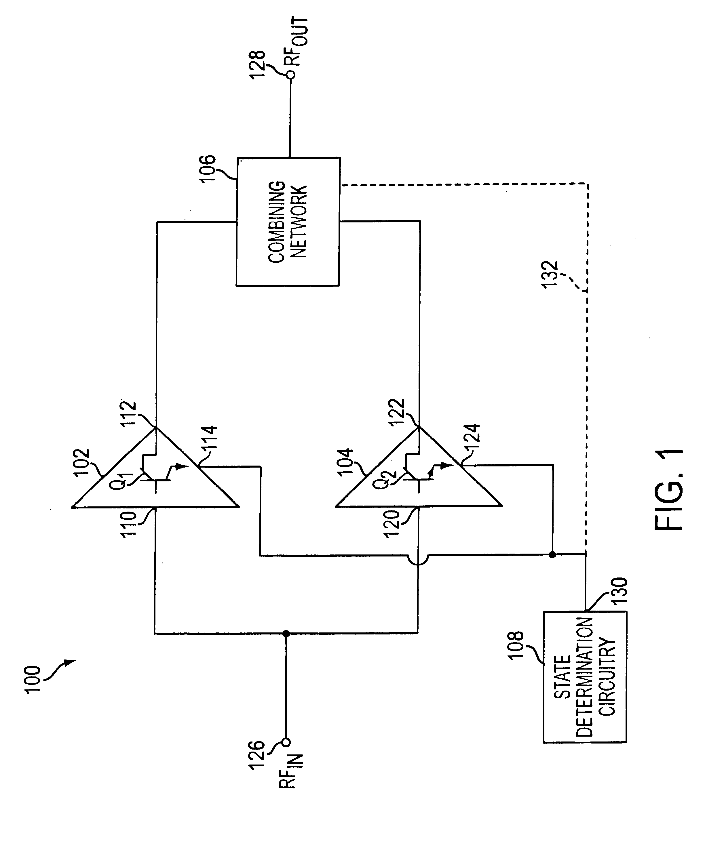
FIG. 1 illustrates a switchable path power amplifier 100 in accordance with a first embodiment of the present invention. The switchable path power amplifier 100 is well suited for applications such as cellular phones, cordless phones, two way pagers, wireless LANs, and AM and FM analog transmitters. As will be appreciated, depending upon the complexity and / or cost of the system, the power amplifier 100 may serve simply as a driver amplifier, or may be the complete power amplifier for the system.

The switchable path power amplifier 100 includes a first power device 102, a second power device 104, a combining network 106, and state determination circuitry 108. In brief, the two power devices 102 and 104 are designed for power efficient operation at two different output power levels. The combining network 106 and the state determination circuitry work together to switch the output path between the two power devices according to the output power level, thereby achieving power efficiency ...


PUM


Abstract

The present invention teaches a power amplifier having two output power devices and a mechanism for switching the output path between these two power devices. The first output power device is designed for power efficient signal amplification at the power amplifier's highest output power level. The second output power device is designed for power efficient signal amplification at the output power level that the power amplifier is most likely to operate. By switching between the two power devices according to the output power level, a high level of power efficiency can be achieved across a broad range of operating states of the power amplifier.

Description

DESCRIPTION1. Technical FieldThe present invention is related to power amplifiers such as those used in cellular communications systems. More specifically, the present invention teaches a power amplifier having at least two output power devices and a mechanism for switching the output path between these two power devices. The first output power device is designed for power efficient signal amplification at the power amplifier's highest output power level. The second output power device is designed for power efficient signal amplification at the output power level that the power amplifier is most likely to operate. By switching between the two power devices according to the output power level, a high level of efficiency can be achieved across a broad range of operating states of the power amplifier.2. Background ArtThe power efficiency of an amplification device such as a transistor varies with operating conditions. For example, a power amplifier designed for power efficiency at one ...

Claims


Application Information

Patent Timeline
IPC IPC(8): H03G1/00H03F3/72H03F1/00H03F3/20
CPCH03G1/0088H03F3/72
Inventor KING, JOEL R.OLSEN, GORDON A.
Owner MAXIM INTEGRATED PROD INC
Why Eureka
Try Eureka