
Vehicle ventilation system

a ventilation system and vehicle technology, applied in vehicle components, vehicle heating/cooling devices, railway heating/cooling, etc., can solve the problems of inability to quickly effect and maintain the hvac system of the vehicle, stagnation and become stale, and cannot be utilized in rainy weather withou

Inactive Publication Date: 2002-03-26
INT TRUCK INTPROP LLC
View PDF22 Cites 63 Cited by
  • Summary
  • Abstract
  • Description
  • Claims
  • Application Information

AI Technical Summary

Benefits of technology

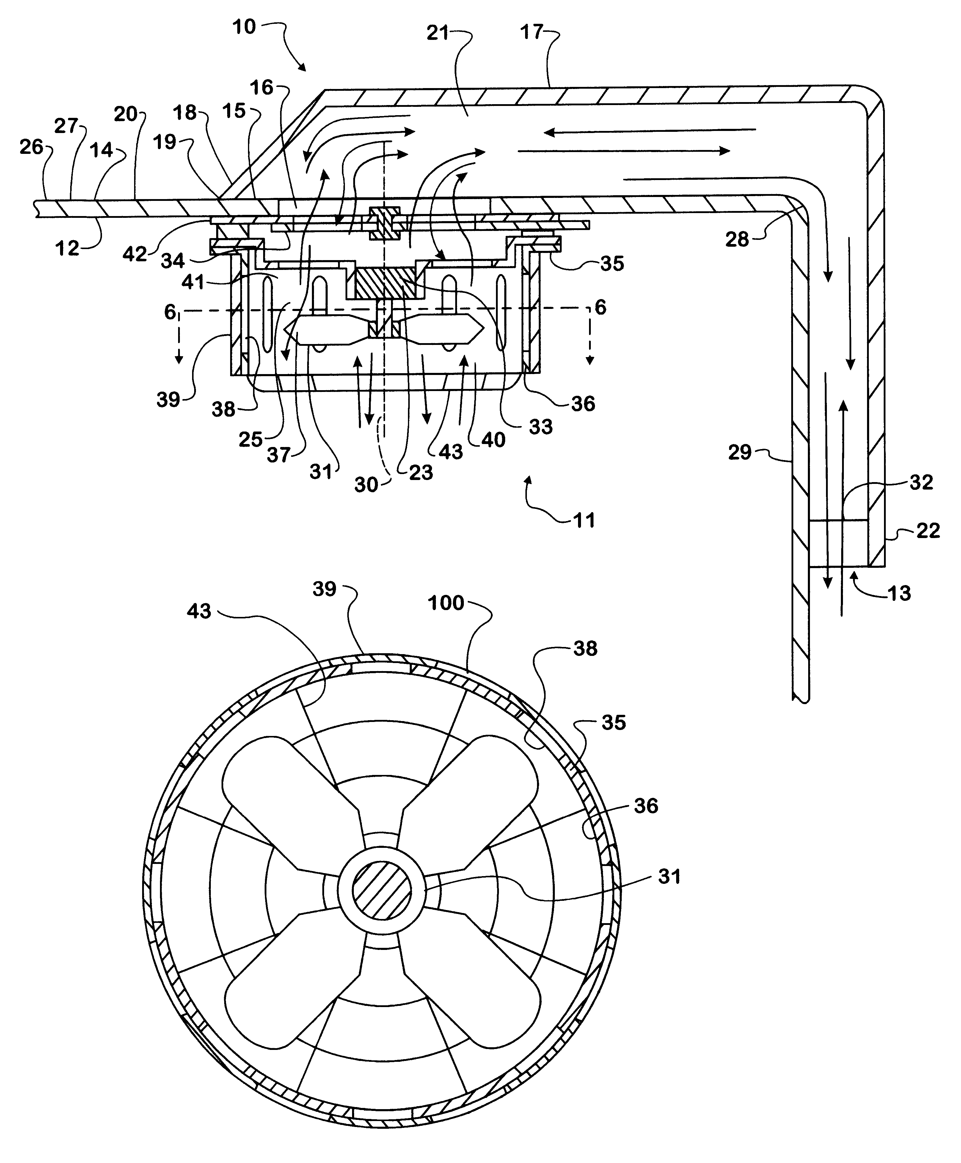
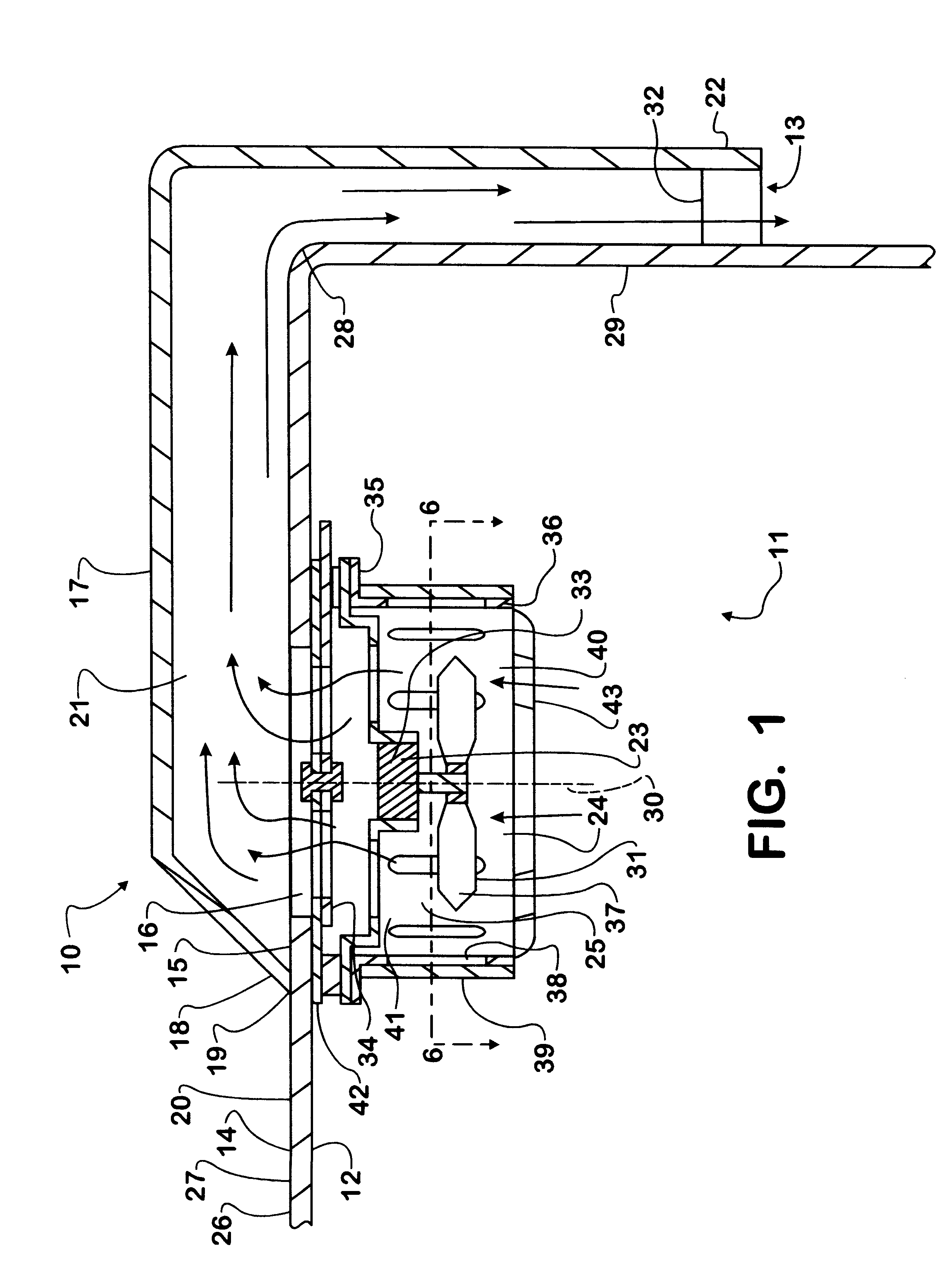
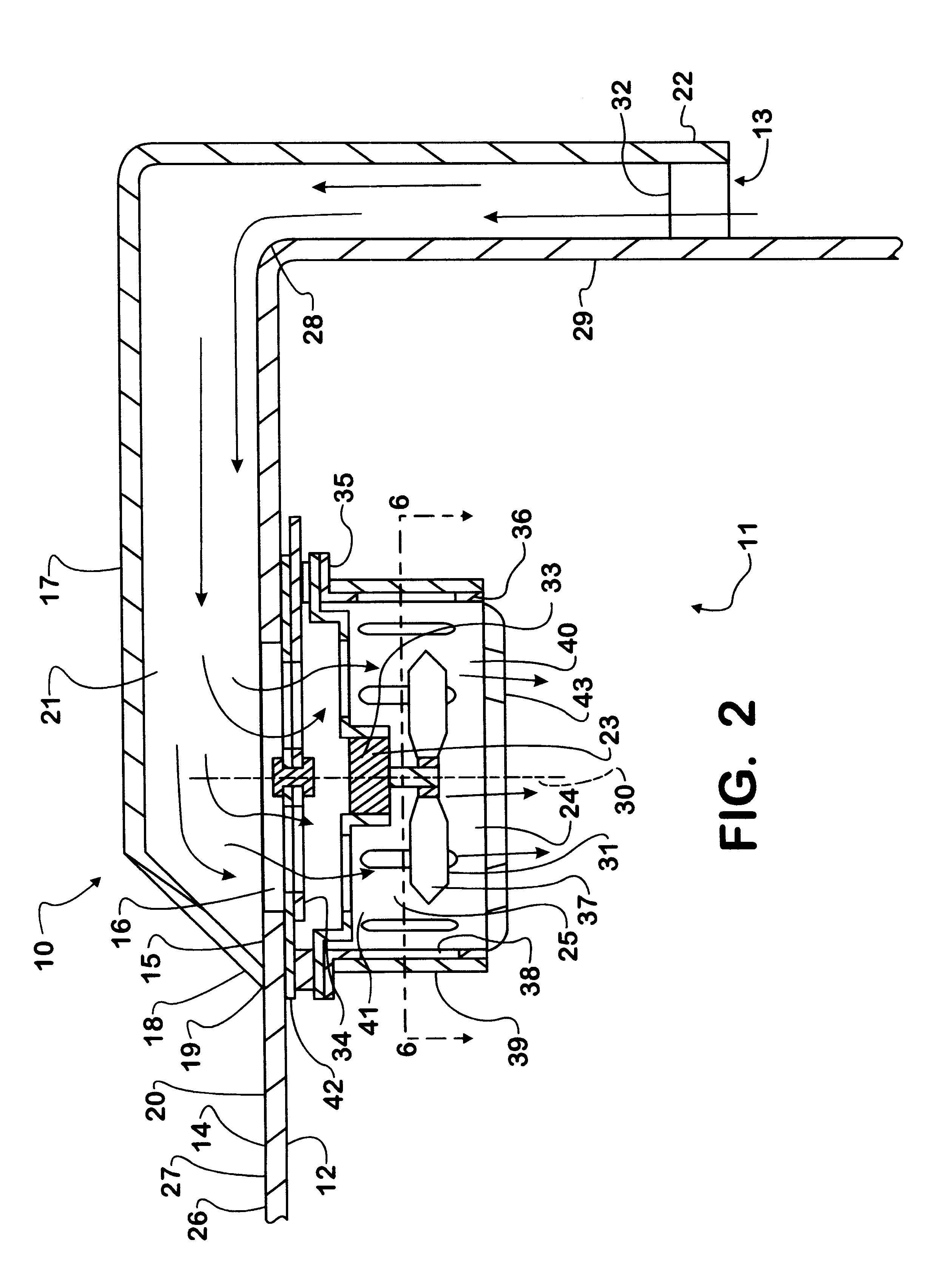
As a result,--an object of the present invention is to provide a ventilation system 10 which is capable of actively or passively moving air between the upper portion of the interior 11 of the occupant cabin 12 and the outside atmosphere 13, whether the vehicle is stationary or in motion, under any weather conditions, without allowing the entry of moisture through the ventilation system 10 into the interior 11 of the vehicle.
Thus the ventilation system 10 of the present invention accomplishes all of its objects. The fan 23 of the ventilation system 10 can be used to actively move air from the upper portion of the interior 11 of the occupant cabin 12, through the ventilation system 10, and into the outside atmosphere 13. This mode of operation of the ventilation system 10 is shown in FIG. 1. If the fan 23 is made to move air in the reverse direction the ventilation system 10 can move air from the outside atmosphere 13, through the ventilation system 10, and into the upper portion of the interior 11 of the occupant cabin 12. When the fan 23 is not in operation the ventilation system 10 passively moves air between the outside atmosphere 13 and the interior 11 of the vehicle's occupant cabin 12. Because the second end 22 of the duct 17 is positioned below the first end 19 of the duct 17, moisture is prevented from entering the interior 11 of the occupant cabin 12 through the ventilation system 10.

Problems solved by technology

Thus, it is often the case that the vehicle's HVAC system is not capable of rapidly effecting and maintaining a comfortable environment in the upper portion of the occupant cabin.
Furthermore, because there is very little replacement of the air in the upper portion of the vehicle's interior, it can stagnate and become stale.
While this system allows for ventilation of the upper portion of the interior of the occupant cabin, it can not be utilized in rainy weather without introducing moisture into the interior of the occupant cabin.

Method used


Image

  • Vehicle ventilation system
  • Vehicle ventilation system
  • Vehicle ventilation system

Examples


Embodiment Construction

There is shown in FIGS. 1-9 a ventilation system 10, and a vehicle 40 for mounting the ventilation system to, in accordance with this invention. The vehicle 40 has a chassis, a suspension engaged to the chassis for supporting the vehicle 40, a powertrain engaged to the chassis for driving the vehicle 40 and an occupant cabin 12 engaged to the chassis for isolating the occupants of the vehicle 40 from the elements. One or more components 15 of the exterior structure 14 of the occupant cabin 12 define an opening 16 through the upper portion of the exterior structure 14 of the occupant cabin 12. Air can move through this opening 16 between the interior 11 of the occupant cabin 12 and outside the occupant cabin 12. A duct 17 is mounted to the vehicle. An outer wall 18 of a first end 19 of the duct 17 is mated to an outer surface 20 of one or more components 15 of the exterior structure 14 of the occupant cabin 12. The outer wall 18 of the first end 19 of the duct 17 surrounds at least a...


PUM


Abstract

A vehicle ventilation system mounted to the upper portion of the exterior structure of a vehicle's occupant cabin. The components of the exterior structure of the occupant cabin define an opening through the exterior structure of the occupant cabin in the upper portion of the occupant cabin. A duct is mounted to the exterior structure of the occupant cabin and has a first end in fluid communication with the opening in the exterior structure of the occupant cabin. A second end of the duct is positioned below the first end of the duct and is open to and in fluid communication with the outside atmosphere. A fan is mounted to the exterior structure of the occupant cabin and is positioned such that when in operation it can be operated to move air through the opening in the exterior structure of the occupant cabin. The fan is controllable to change the rate and direction of the flow of air which it creates. A first rotary damper is mounted over the opening in the exterior structure of the occupant cabin and can be selectively opened or closed to allow or prevent air flow through the opening in the exterior structure of the occupant cabin. A second damper is mounted in a position such that it radially surrounds the impeller of the fan and can be used to control the flow of air radially outward from or radially inward toward the impeller of the fan.

Description

This invention relates to a ventilation system for a vehicle. More specifically, the invention relates to a ventilation system, which is capable of actively or passively moving air between the upper region of the interior of the vehicle and the atmosphere outside the vehicle as well as circulating air within the upper region of the interior of the vehicle. The ventilation system is capable of actively moving air between the interior of the vehicle and the outside atmosphere whether the vehicle is stationary or moving. The ventilation system is also capable of actively or passively moving air between the interior of the vehicle and the outside atmosphere in rainy weather while preventing the entry of moisture through the ventilation system into the interior of the vehicle.RELATED ARTIn vehicles which have occupant cabins with high ceilings and heating ventilation and air conditioning (HVAC) systems with supply and return ducts concentrated near the lower portion of the occupant cabin...

Claims


Application Information

Patent Timeline
Patent Type & Authority Patents(United States)
IPC IPC(8): B60H1/24B60H1/26
CPCB60H1/262
Inventor TOSCONI, JAMES J.MATTES, PATRICK J.
Owner INT TRUCK INTPROP LLC
Learn More