Apparatus for determining metal CMP endpoint using integrated polishing pad electrodes

a technology of polishing pad electrodes and endpoints, which is applied in the field of apparatus and methods for determining the endpoint of metal cmp polishing process using integrated polishing pad electrodes, can solve the problems of insufficient determination of the endpoint of a polishing process, lack of existing control techniques, and several shortcomings of the endpoint detection technique of wafer polishing process

Inactive Publication Date: 2002-04-09
ADVANCED MICRO DEVICES INC
View PDF6 Cites 183 Cited by
  • Summary
  • Abstract
  • Description
  • Claims
  • Application Information

AI Technical Summary

Problems solved by technology

The existing endpoint detection techniques for wafer polishing processes, however, suffer from several shortcomings.
For example, because of semiconductor process variations, such as surface non-uniformity of a wafer, existing control techniques may inadequately determine endpoint for a polishing process.
With these techniques, endpoint may be prematurely determined.
With these techniques, any residual process layer located at the center of the wafer may not be detected.
Unfortunately, the problems experienced with traditional endpoint control techniques may be exacerbated when polishing metal or other electrically conductive process layers.
For example, small residual patches of metal remaining on a surface of a wafer, if not detected, may result in electrical shorts or other parametric failures in the final semiconductor devices (e.g., microprocessors, microcontrollers, memory, etc.) Moreover, such residual patches of metal or other conductive process layers, if not removed, may significantly reduce production yield, thus, increasing manufacturing costs.

Method used


Image

  • Apparatus for determining metal CMP endpoint using integrated polishing pad electrodes
  • Apparatus for determining metal CMP endpoint using integrated polishing pad electrodes
  • Apparatus for determining metal CMP endpoint using integrated polishing pad electrodes

Examples


Embodiment Construction

Illustrative embodiments of the invention are described below. In the interest of clarity, not all features of an actual implementation are described in this specification. It will of course be appreciated that in the development of any such actual embodiment, numerous implementation-specific decisions must be made to achieve the developers' specific goals, such as compliance with system-related and business-related constraints, which will vary from one implementation to another. Moreover, it will be appreciated that such a development effort might be complex and time-consuming, but would nevertheless be a routine undertaking for those of ordinary skill in the art having the benefit of this disclosure.

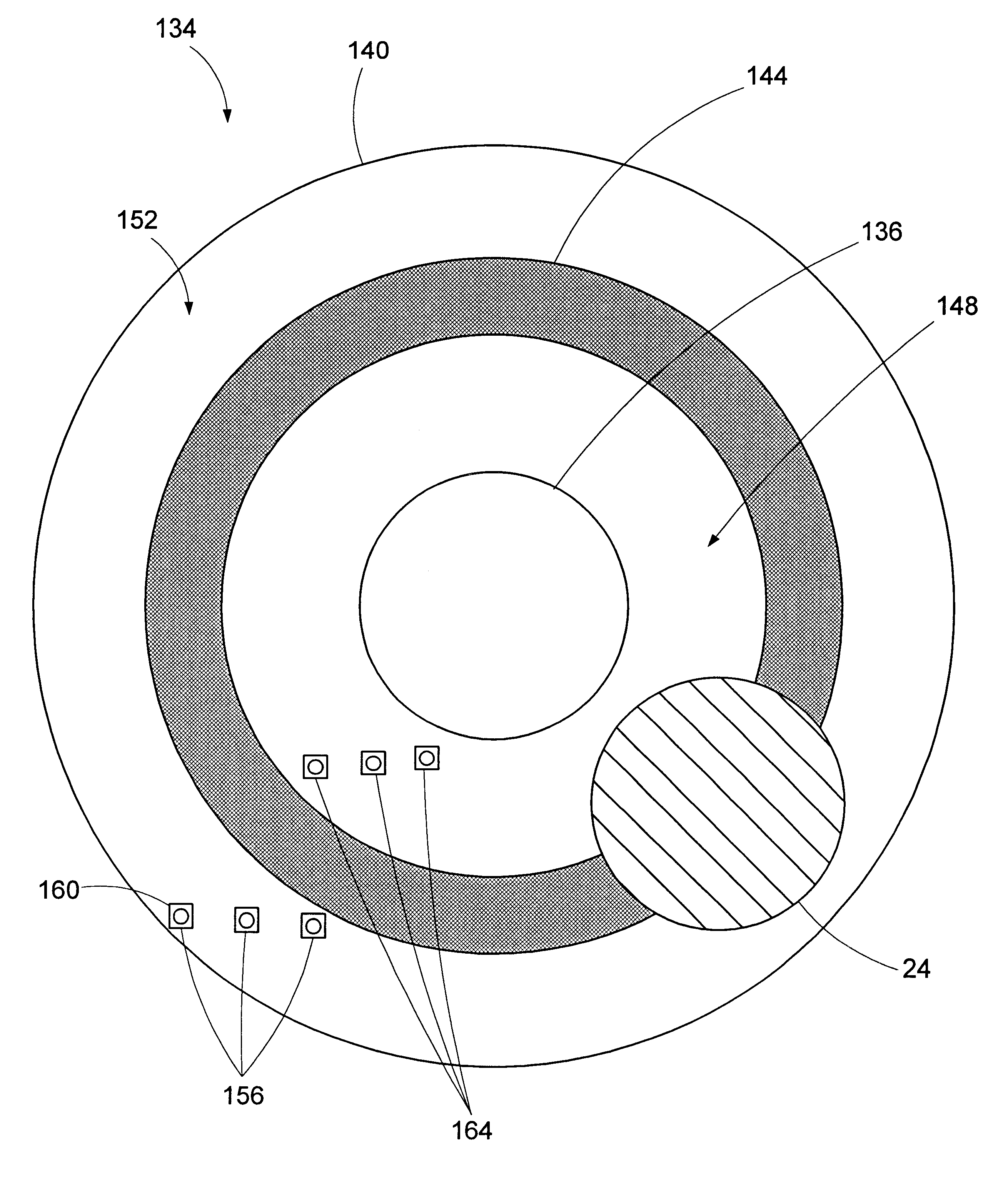
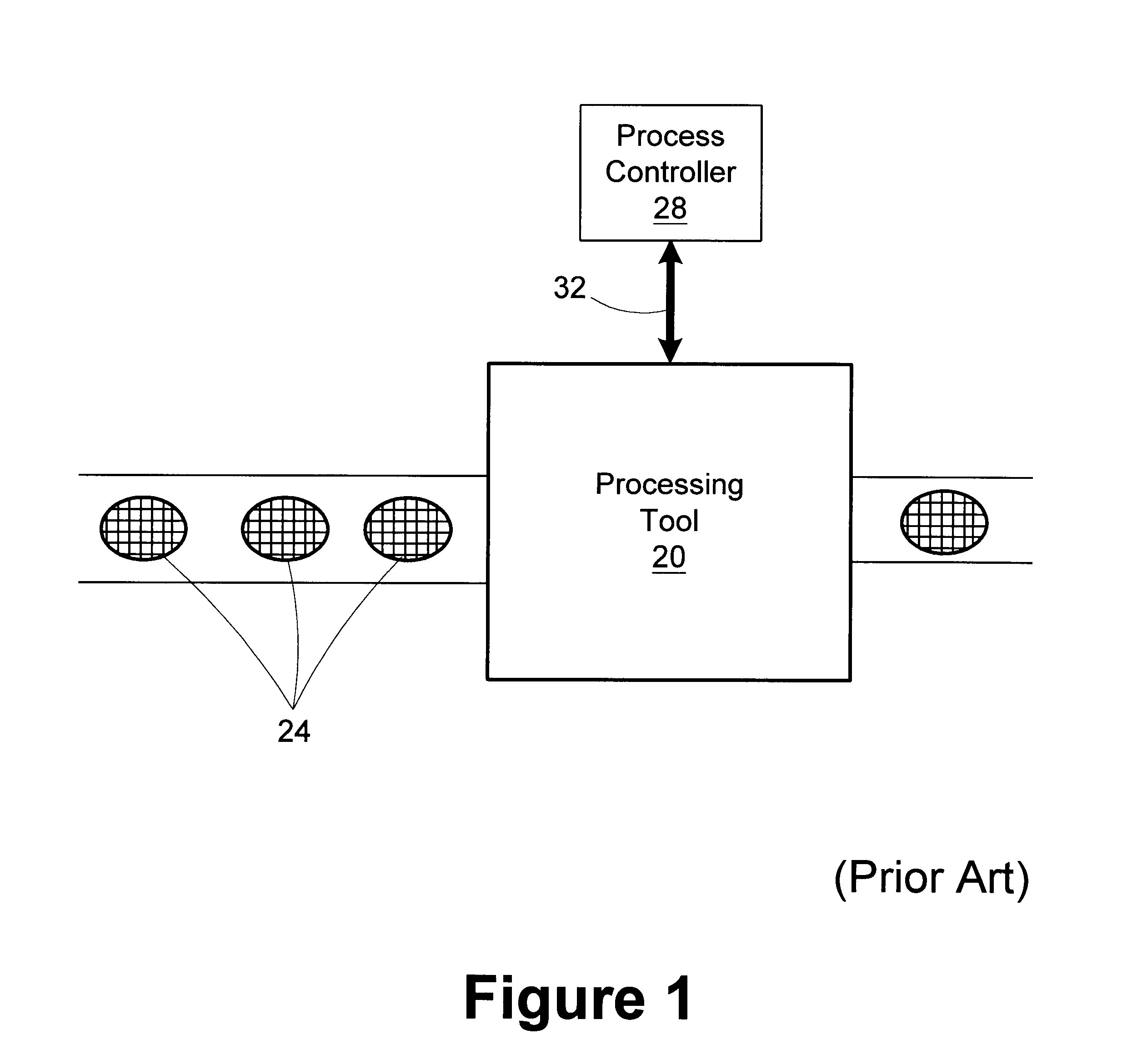
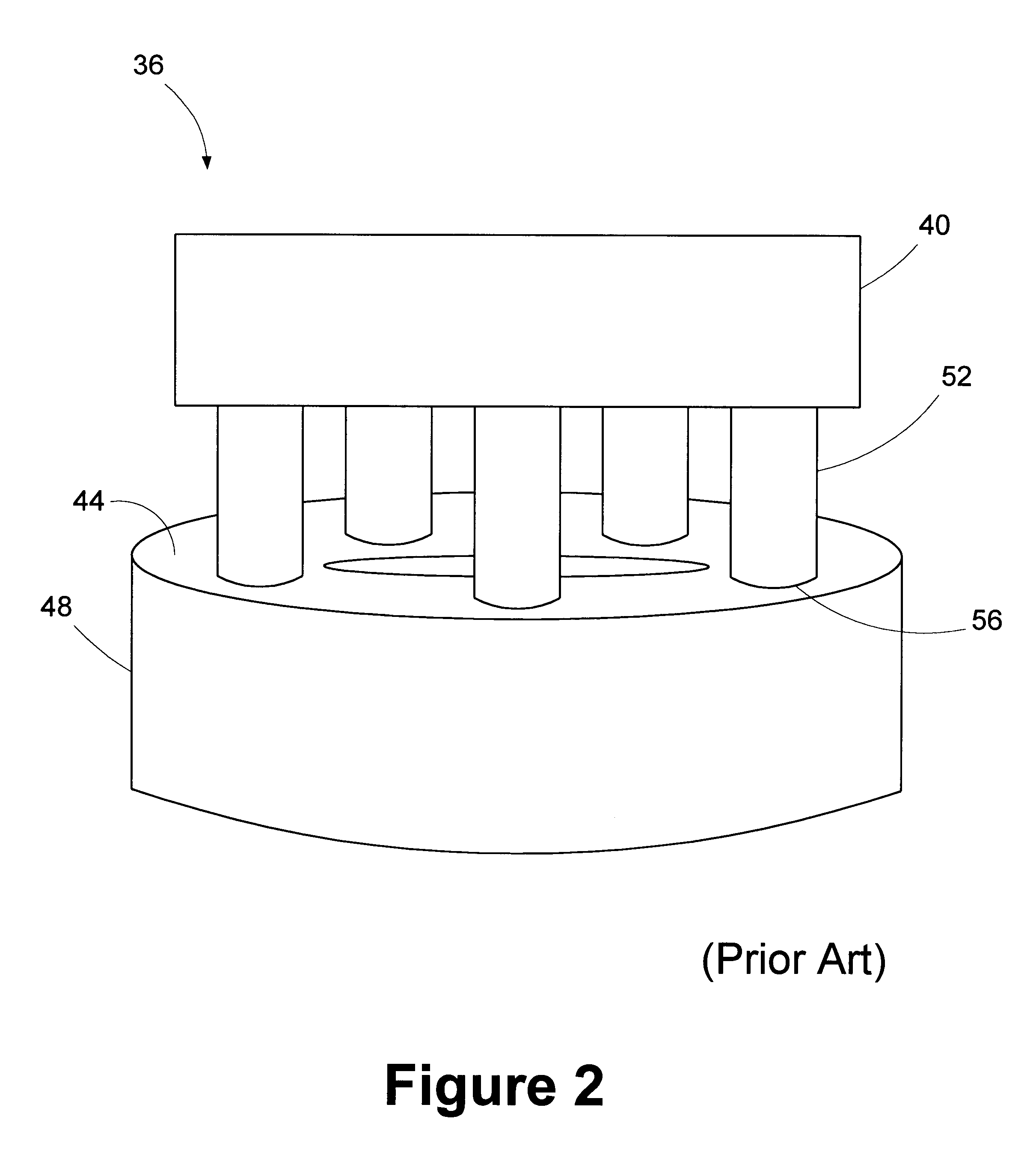
The present invention is directed to a method and apparatus for determining endpoint of a semiconductor polishing process. In disclosing the present invention, reference will be made to the illustrative embodiment of the invention depicted in FIGS. 1-10. The relative sizes of the vario...


PUM


Abstract

A polishing system includes a polishing tool having a platen, a polishing pad, and a controller. The platen is adapted to have the polishing pad attached thereto. The polishing pad includes a polishing surface and a back surface that is opposite the polishing surface. At least one sender electrode and at least one response electrode is disposed in the polishing pad. The controller is coupled to the polishing tool. A method includes polishing a conductive process layer of a wafer using a polishing pad of a polishing tool having at least one sender electrode and at least one response electrode disposed therein. A signal is provided to the at least one sender electrode. The signal provided to the at least one sender electrode is monitored with at least one of a group of the at least one response electrode, the at least one response electrode communicating with the at least one sender electrode through the conductive process layer of the wafer. Endpoint of the polishing process is determined based on the signal received by the at least one response electrode.

Description

1. Field of the InventionThis invention relates generally to semiconductor processing, and more particularly, to a method and apparatus for determining metal chemical mechanical polishing (CMP) endpoint using integrated polishing pad electrodes.2. Description of the Related ArtCMP is a widely used means of planarizing silicon dioxide as well as other types of processing layers on semiconductor wafers. Chemical mechanical polishing typically utilizes an abrasive slurry disbursed in an alkaline or acidic solution to planarize the surface of the wafer through a combination of mechanical and chemical action. Generally, a chemical mechanical polishing tool includes a polishing device positioned above a rotatable circular platen or table on which a polishing pad is mounted. The polishing device may include one or more rotating carrier heads to which wafers may be secured, typically through the use of vacuum pressure. In use, the platen may be rotated and an abrasive slurry may be disburse...

Claims


Application Information

Patent Timeline
Patent Type & Authority Patents(United States)
IPC IPC(8): B24B37/04B24B49/10B24B49/04B24B49/02B24B37/013B24B37/12B24B37/20
CPCB24B37/013B24B37/12B24B49/10B24B49/04B24B37/20
Inventor BECKAGE, PETER J.
Owner ADVANCED MICRO DEVICES INC
Why Eureka
Try Eureka