Switch modules, a switch matrix including such modules, and a non-blocking modular switch network including such a matrix

a switch matrix and switch technology, applied in data switching networks, time-division multiplexing selection, instruments, etc., can solve the problems of not being able to avoid installing all, not being able to implement optical switch networks of greater than 128.times.128, and not being able to implement all known clos networks. achieve the effect of increasing capacity

Inactive Publication Date: 2002-04-09
ALCATEL LUCENT SAS
View PDF6 Cites 6 Cited by
  • Summary
  • Abstract
  • Description
  • Claims
  • Application Information

AI Technical Summary

Benefits of technology

The object of the invention is to provide a matrix capable of having greater capacity, and a switch network that can operate even if it is under-equipped.
The matrix characterized in this way has interconnections between the r modules of the first stage and the r modules of the second stage which still cross over, but which are mutually parallel in groups of 2p links. It is thus possible to use ribbons each grouping together 2p optical fibers in parallel. The number of crossovers is thus greatly reduced. The saving in bulk occupied enables matrices of larger size to be implemented, in particular 256.times.256 and 512.times.512 matrices to be implemented.
The network characterized in this way presents the advantage of being capable of operating even if it is under-equipped.

Problems solved by technology

The space occupied by these crossing fibers constitutes a technological limitation which makes it impossible in practice to implement optical switch networks of size greater than 128.times.128.
Furthermore, known Clos networks cannot be under-equipped, i.e. it is not possible to avoid installing all of the matrices in the central stage even if the full capacity of a complete network is not required immediately, and this is because known networks cannot operate if any matrix in the central stage is missing.

Method used


Image

  • Switch modules, a switch matrix including such modules, and a non-blocking modular switch network including such a matrix
  • Switch modules, a switch matrix including such modules, and a non-blocking modular switch network including such a matrix
  • Switch modules, a switch matrix including such modules, and a non-blocking modular switch network including such a matrix

Examples


Embodiment Construction

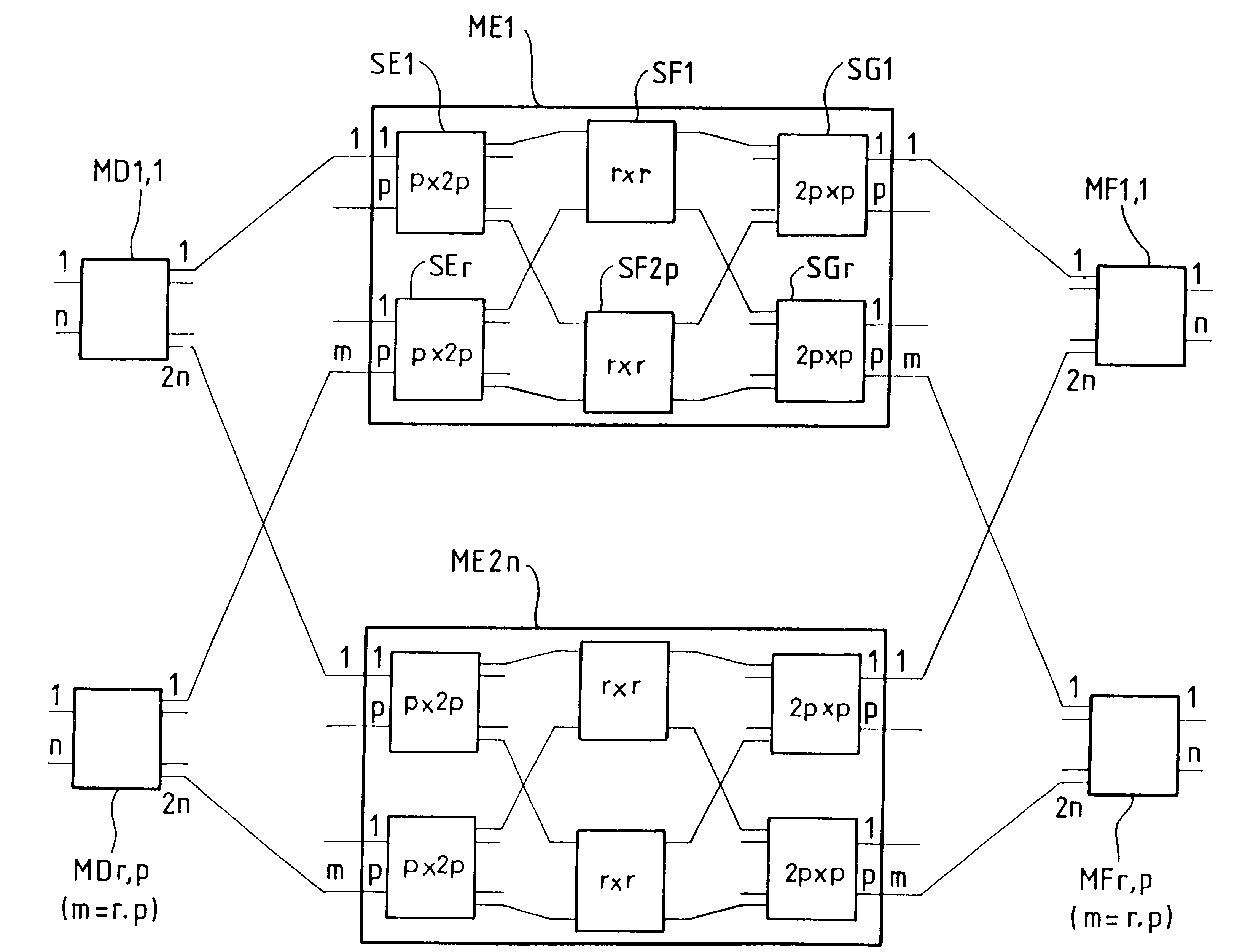
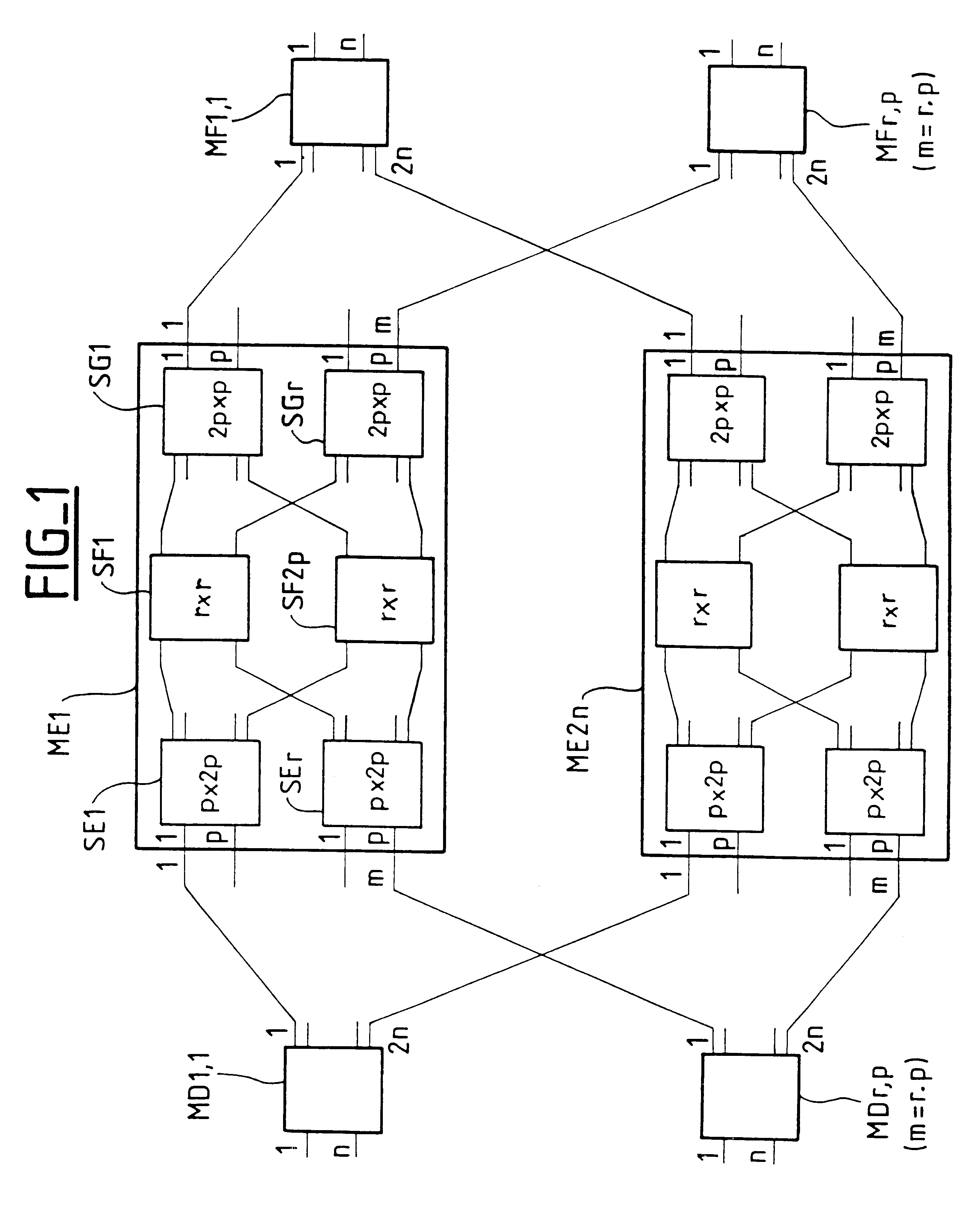
The network shown in FIG. 1 is an n.m inlet by n.m outlet network. The number m is equal to r.p where r and p are two integers. This network comprises:

a first stage constituted by m non-blocking matrices MD1,1; . . . ; MDr,p, each having n inlets and 2n outlets, the inlets constituting the inlets of the network;

a second stage constituted by 2n non-blocking matrices ME1, . . . , ME2n, each having m inlets and m outlets; and

a third stage constituted by m non-blocking matrices MF1,1; . . . ; MFr,p, each having 2n inlets and n outlets, the outlets constituting the outlets of the network.

The m inlets of each matrix of the second stage ME1, . . . , ME2n are connected to respective outlets of each of the matrices of the first stage MD1,1; . . . ; MDr,p. The m outlets of each matrix of the second stage ME1, . . . , ME2n, are connected to respective inlets of each of the matrices of the third stage MF1,1; . . . ; MFr,p.

All of the matrices of the second stage have the same conventional struct...


PUM


Abstract

The matrix comprises:a first stage having r switch modules each having 2p2 inlets and 2p.r outlets; anda second stage comprising r switch modules each having 2p.r inlets and 2p2 outlets.The outlets of the first stage are connected to inlets of the second stage via links which are mutually parallel in groups of 2p links, thereby reducing the number of crossover points, and thus reducing size. If the matrix is implemented using photonic technology, these links are implemented by means of optical fiber ribbons. The invention is applicable to photonic switch networks.

Description

The invention relates to switch modules suitable for making a non-blocking switch network, more particularly adapted for photonics. Nevertheless, it can also be used for making switch networks with electronic technology.It is known that a non-blocking switch network having n.m inlets and n.m outlets, i.e. equivalent to a matrix having n.m inlets and n.m outlets can be made by using a plurality of stages each constituted by non-blocking switch matrices of size that is smaller than that of the network to be made. Such a non-blocking network is said to be a Clos network when it comprises:a first stage constituted by c matrices, each having a inlets and b outlets;a second stage constituted by b matrices, each having c inlets and c outlets; anda third stage constituted by c matrices, each having b inlets and a outlets where b.gtoreq.2a-1.By way of example, the article "Multistage optoelectronic switch networks", by R. I. MacDonald et al., 8049.sub.j IEEE Proceedings-J Optoelectronics 141...

Claims


Application Information

Patent Timeline
Patent Type & Authority Patents(United States)
IPC IPC(8): H04L12/56H04Q11/00H04Q3/52H04L12/931H04L12/933H04Q11/04
CPCH04L49/1515H04Q11/0001H04L49/357
Inventor LEBOUETTE, CLAUDESOTOM, MICHELOLLIVIER, FRAN.CEDILLA.OIS-XAVIER
Owner ALCATEL LUCENT SAS
Why Eureka
Try Eureka