Holder including a hydraulic piston for the detachable assembly of cutting tools

a technology of hydraulic piston and detachable assembly, which is applied in the direction of attachable milling devices, auxilary equipment, manufacturing tools, etc., and can solve problems such as mastering in practi

Inactive Publication Date: 2002-04-16
SANDVIK INTELLECTUAL PROPERTY AB
View PDF4 Cites 15 Cited by
  • Summary
  • Abstract
  • Description
  • Claims
  • Application Information

AI Technical Summary

Benefits of technology

The present invention aims at obviating the above-mentioned problems in previously known tool holders and at providing a tool holder which, in a reliable way, can bring about a distinct self-locking of the wedge bodies in connection with the clamping of a tool; all with the purpose of guaranteeing that the tensile force which is exerted by the piston device in connection with the clamping is maintained without interruption, even after the oil pressure has been relieved.

Problems solved by technology

A problem difficult to master in practice in previously known tool holders has, however, been to guarantee a distinct self-locking of the wedge bodies when the piston is brought to the rear end position thereof for fixing the tool in the holder.

Method used


Image

  • Holder including a hydraulic piston for the detachable assembly of cutting tools
  • Holder including a hydraulic piston for the detachable assembly of cutting tools
  • Holder including a hydraulic piston for the detachable assembly of cutting tools

Examples


Embodiment Construction

A) Conventional Structure

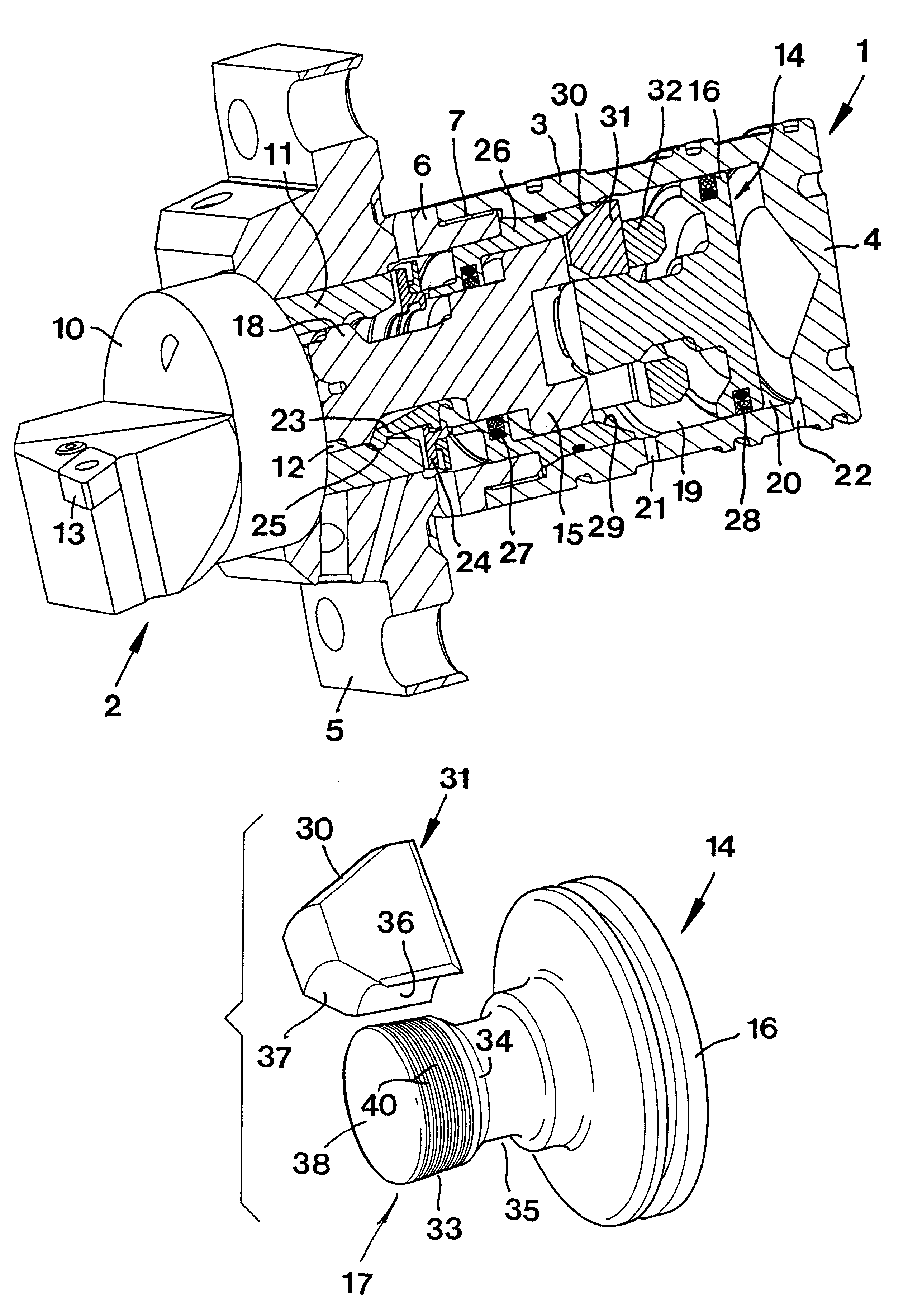
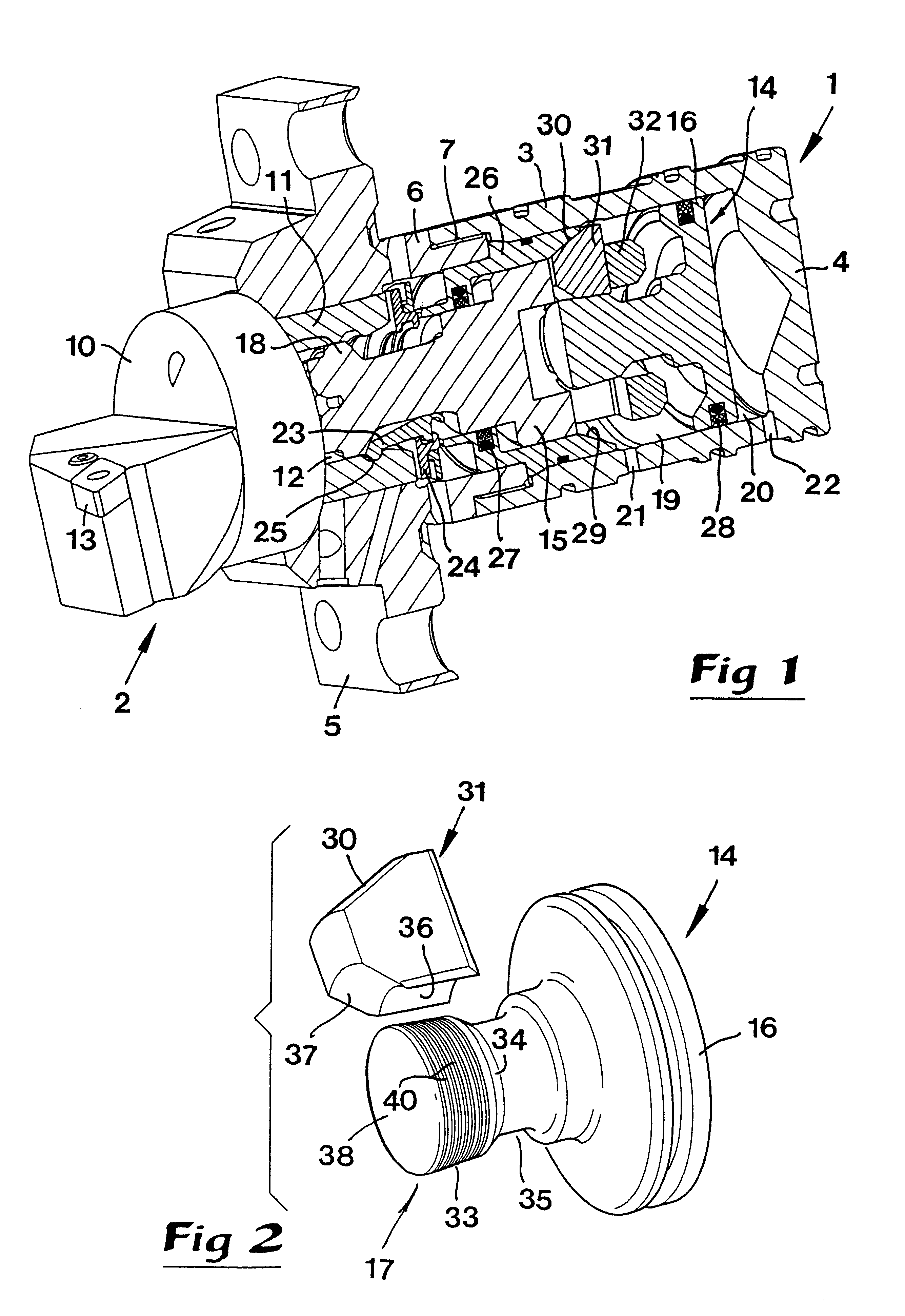
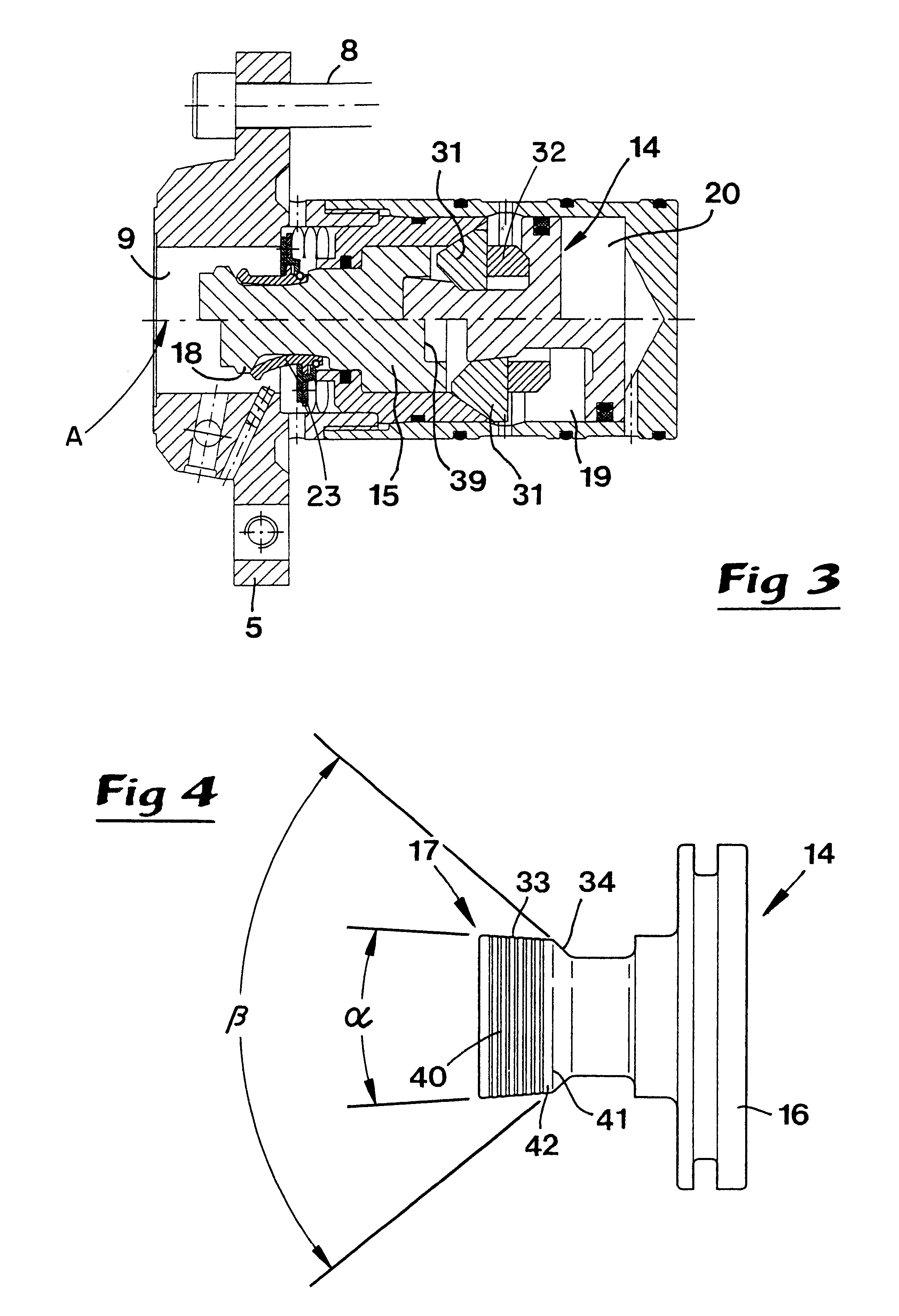
In FIG. 1, numeral 1 generally designates a tool holder in which a tool 2 may be detachably mounted. The holder is in the shape of a cylindrical housing composed of rear and front parts. The rear part comprises a cylinder 3 and an end wall 4. The front part includes a flange 5 and a sleeve 6 extending backwards therefrom. The housing defines a longitudinal center axis A. The sleeve 6 is connected to the cylinder 3 via a threaded joint 7. In the flange 5, which may be fixed in the machine by means of screws 8 (see FIG. 3), a central hole 9 is formed, which serves as a grip for the tool 2.

The tool 2 comprises, in addition to a head 10, a part 11 in the form of a short tubular sleeve piece extending backwards from the head, which tube piece defines a female-like, rearwardly opening port 12. In practice, the outer envelope surface of the sleeve 11, as well as the inner surface of the hole 9, may be shaped as polygonal in cross section, and rearwardly tapering in...


PUM

PropertyMeasurementUnit
cone angleaaaaaaaaaa

Abstract

A holder for the detachable assembly of cutting tools includes a clamping mechanism, which has a piston axially movable by applying oil pressure on either of two opposite sides thereof. A projection of the piston includes a cone surface with a moderate cone angle arranged to co-operate with a wedge body which is self-locking in relation to the cone surface to keep the cutting tool clamped, even when oil pressure is relieved. In order to guarantee such self-locking, transverse grooves are provided in the cone surface enabling friction-reducing oil to be evacuated from the interface between the cone surface and an inner, partially cone-shaped surface on the wedge body.

Description

This invention relates to a holder intended for the detachable assembly of cutting tools, which comprises a housing and a clamping mechanism arranged therein.A conventional clamping mechanism includes a male element arranged for engagement in a female-like opening in the tool, the male element being movable backwards and forwards in relation to a bushing included in the housing. The male element moves between an inner end position in which the tool is clamped in relation to the housing, and an outer end position in which the tool is detachable from the housing. The male element is moved by means of a piston which is movable backwards and forwards in a cavity inside the housing and which separates outer and inner chambers to and from which hydraulic oil may be fed in order to move the male element up against either of said end positions. The piston includes a projection with an outer, rearwardly converging first cone surface for co-operation with a number of tangentially spaced wedge...

Claims


Application Information

Patent Timeline
Patent Type & Authority Patents(United States)
IPC IPC(8): B23B31/30B23B29/04B23B29/00B23B31/02B23B31/26B23Q3/12
CPCB23B29/046B23B31/261B23B31/30Y10T82/2589Y10T279/1291Y10T82/2591Y10T82/266Y10T82/2597Y10T409/309464B23B2260/146B23B2231/12B23B29/00
Inventor SKOOG, ANDERS
Owner SANDVIK INTELLECTUAL PROPERTY AB
Why Eureka
Try Eureka