Vehicle air conditioner

a technology for air conditioners and vehicles, applied in the field of vehicles, can solve the problems of windshield fogged, air having a high humidity and the temperature of air blown into the passenger compartment becomes lower

Inactive Publication Date: 2002-04-16
DENSO CORP
View PDF9 Cites 30 Cited by
  • Summary
  • Abstract
  • Description
  • Claims
  • Application Information

AI Technical Summary

Benefits of technology

According to the present invention, a vehicle air conditioner includes an air conditioning case for defining an air passage through which air is blown into a passenger compartment, a partition member for partitioning the air passage into a first air passage through which outside air outside the passenger compartment flows into a defroster opening and a second air passage through which inside air inside the passenger compartment flows into a foot opening during a double layer flow mode, a refrigerant cycle through which refrigerant flows, and a control unit. The refrigerant cycle includes a compressor for compressing and discharging refrigerant, a condenser for condensing refrigerant discharged from the compressor during a cooling mode, a first pressreducing unit for decompressing refrigerant from the condenser, a heat exchanger disposed in the air conditioning case for cooling air passing therethrough and for evaporating refrigerant from the first press-reducing unit during the cooling mode, a hot-gas bypass passage through which refrigerant discharged from the compressor is directly introduced into the evaporator while bypassing the condenser and the first press-reducing unit during a heating mode, a second press-reducing unit disposed in the hot-gas bypass passage for decompressing refrigerant discharged from the compressor, and a valve unit for switching a flow direction of refrigerant discharged from the compressor. In the vehicle air conditioner, when the heating mode is set, the double layer flow mode is set. Thus, even when re-evaporation of condensed water on the heater exchanger is generated during the heating mode, vaporized water is mainly blown toward the lower side of the passenger compartment from the foot opening and is hardly blown toward a windshield from the defroster opening, because inside air has a greatly high absolute humidity as compared with outside air. As a result, it can prevent the windshield from being fogged due to vaporization of the condensed water on the heat exchanger.
Preferably, during the cooling mode, the valve unit opens the inlet side of the condenser and closes the inlet side of the hot-gas bypass passage. Further, during the heating mode, the valve unit closes the inlet side of the condenser and opens the inlet side of the hot-gas bypass passage. Thus, the cooling mode and the heating mode of the refrigerant cycle are readily switched in the heat exchanger.

Problems solved by technology

In this case, when temperature of hot water is low, temperature of air blown into a passenger compartment becomes lower and necessary heating capacity is not proposed for the passenger compartment.
Therefore, air having a high humidity is blown into the passenger compartment, and the windshield may be fogged again.
Further, even when the heating mode is not switched immediately after the cooling mode, when the heating mode with the hot-gas refrigerant bypassing is performed when the condensed water stays on the evaporator, the windshield may be fogged.
However, in the conventional air conditioner, the cooling mode and the heating mode of the refrigerant cycle are not switched by a single heat exchanger, and the problem that the windshield is fogged with operation of the heating mode is not described any.

Method used


Image

  • Vehicle air conditioner
  • Vehicle air conditioner
  • Vehicle air conditioner

Examples


Embodiment Construction

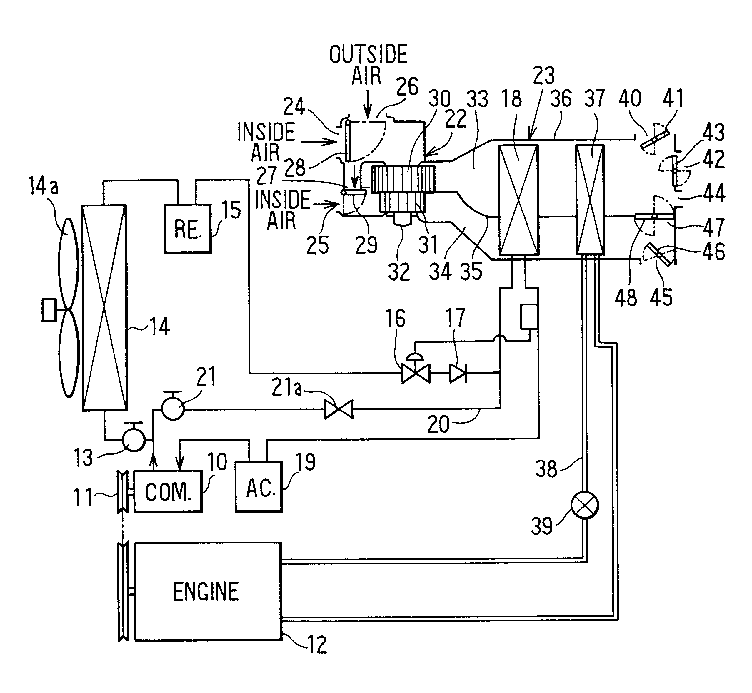
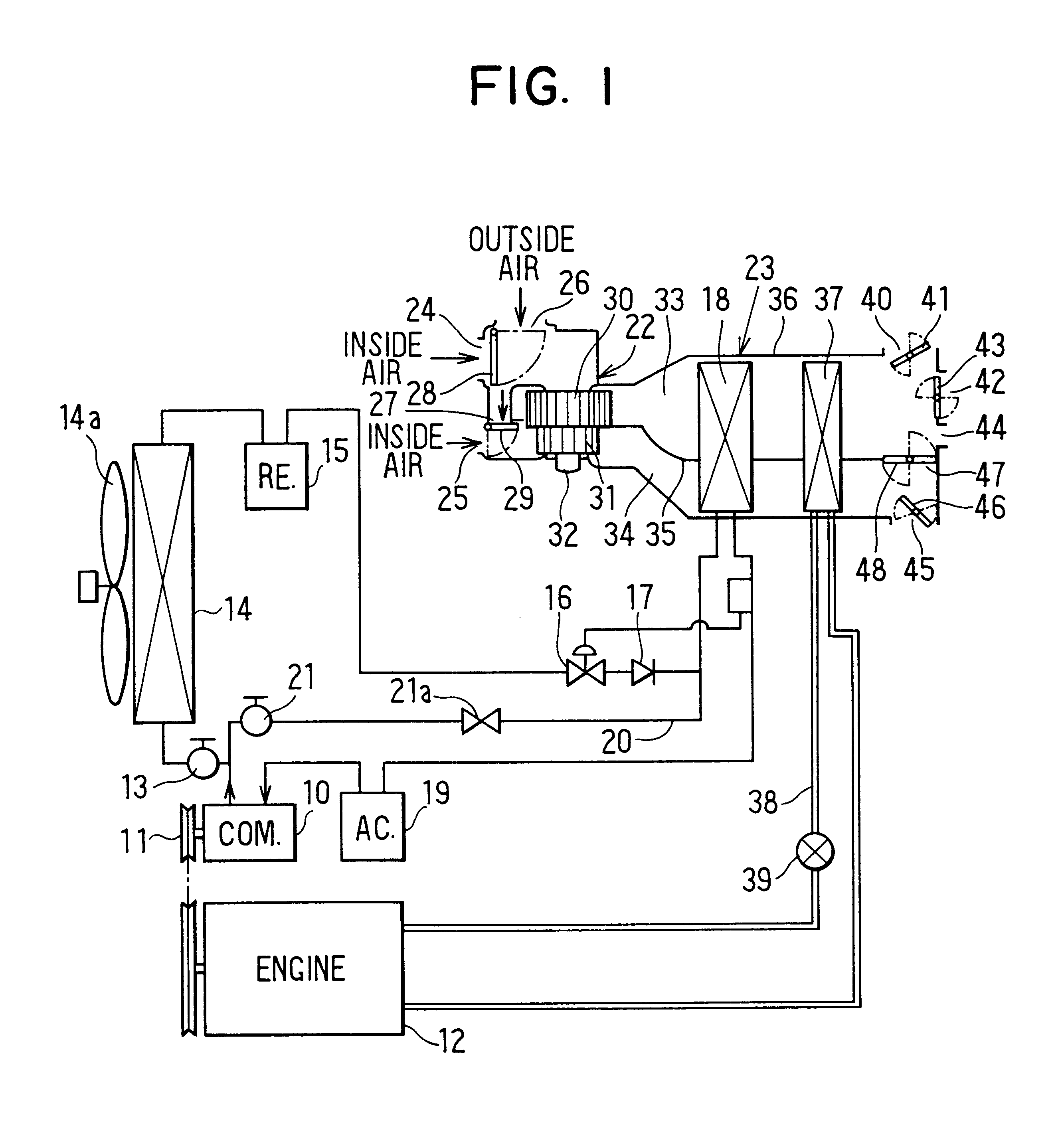
A preferred embodiment of the present invention will be described hereinafter with reference to the accompanying drawings. As shown in FIG. 1, a compressor 10 is driven by a vehicle engine 12 through an electromagnetic clutch 11. A refrigerant discharge side of the compressor 10 is connected to a condenser 14 through a first electromagnetic valve 13, and a refrigerant outlet side of the condenser 14 is connected to a receiver 15 in which liquid refrigerant is separated from gas refrigerant and is stored therein. Outside air outside the passenger compartment is blown toward the condenser 14 by an electrically driven cooling fan 14a. A refrigerant outlet side of the receiver 15 is connected to a thermal expansion valve 16, and a refrigerant outlet side of the thermal expansion valve (first press-reducing unit) 16 is connected to an evaporator 18 through a check valve 17. A refrigerant outlet side of the evaporator 18 is connected to a refrigerant suction side of the compressor 10 thro...


PUM


Abstract

In a vehicle air conditioner, during a cooling mode of a refrigerant cycle, refrigerant discharged from a compressor passes through a condenser and flows into a heat exchanger used as an evaporator after being press-reduced in a first press-reducing unit. On the other hand, during a heating mode of the refrigerant cycle, refrigerant discharged from the compressor is directly introduced into the heat exchanger used as a radiator after being press-reduced in a second press-reducing unit, while bypassing the condenser and the first press-reducing unit. During the heating mode or during the cooling mode when outside air temperature is low, a double layer flow mode is set so that outside air flows toward a defroster opening through a first air passage and inside air flows toward a foot opening through a second air passage partitioned from the first air passage. Thus, it can prevent a windshield from being fogged due to vaporization of condensed water on the heater exchanger during the heating mode.

Description

This application is related to and claims priority from Japanese Patent Application No. Hei. 10-334390 filed on Nov. 25, 1998, the contents of which are hereby incorporated by reference.1. Field of the Invention:The present invention relates to a vehicle air conditioner having a hot-gas bypass function, in which hot-gas refrigerant discharged from a compressor is decompressed and is directly introduced into an evaporator while bypassing a condenser during a heating mode. More particularly, the present invention relates to a control unit which prevents a windshield from being fogged due to vaporization of condensed water on the evaporator when an operation mode of a refrigerant cycle is switched from a cooling mode to the heating mode.2. Description of Related Art:In a conventional vehicle air conditioner, hot water (engine-cooling water) is introduced into a heating heat exchanger in winter so that air is heated in the heating heat exchanger using hot water as a heating source. In t...

Claims


Application Information

Patent Timeline
Patent Type & Authority Patents(United States)
IPC IPC(8): B60H1/00B60H1/22B60H1/32
CPCB60H1/00914
Inventor TAKANO, YOSHIAKIIZAWA, SATOSHI
Owner DENSO CORP
Why Eureka
Try Eureka