Combustion process applicable to the manufacture of cement

Inactive Publication Date: 2002-04-23
LAIR LIQUIDE SA POUR LETUDE & LEXPLOITATION DES PROCEDES GEORGES CLAUDE
7 Cites 12 Cited by

AI-Extracted Technical Summary

Problems solved by technology

If the distance traveled in the kiln is to...

Benefits of technology

In general, the energy of the primary flame will be as low as possible and will represent at most 30% and Preferably at most 15% of the total energy provided by the flame. Preferably, the energy of the primary flame will represent between approx...

Abstract

Combustion process especially applicable to cement works, in which process it is desired to use fuels which are difficult to ignite. To do so, a flame comprising a primary zone and a secondary zone is created. The hot primary zone is created using an oxy-fuel flame, which makes it possible to preheat the fuel which is difficult to ignite so as to raise it to the suitable temperature in the secondary zone where it burns, with air, in order to create the main flame. Applications: cement, metallurgy, glass, etc.

Application Domain

Technology Topic

Oxy-fuelEngineering +2

Image

  • Combustion process applicable to the manufacture of cement
  • Combustion process applicable to the manufacture of cement
  • Combustion process applicable to the manufacture of cement

Examples

  • Experimental program(1)

Example

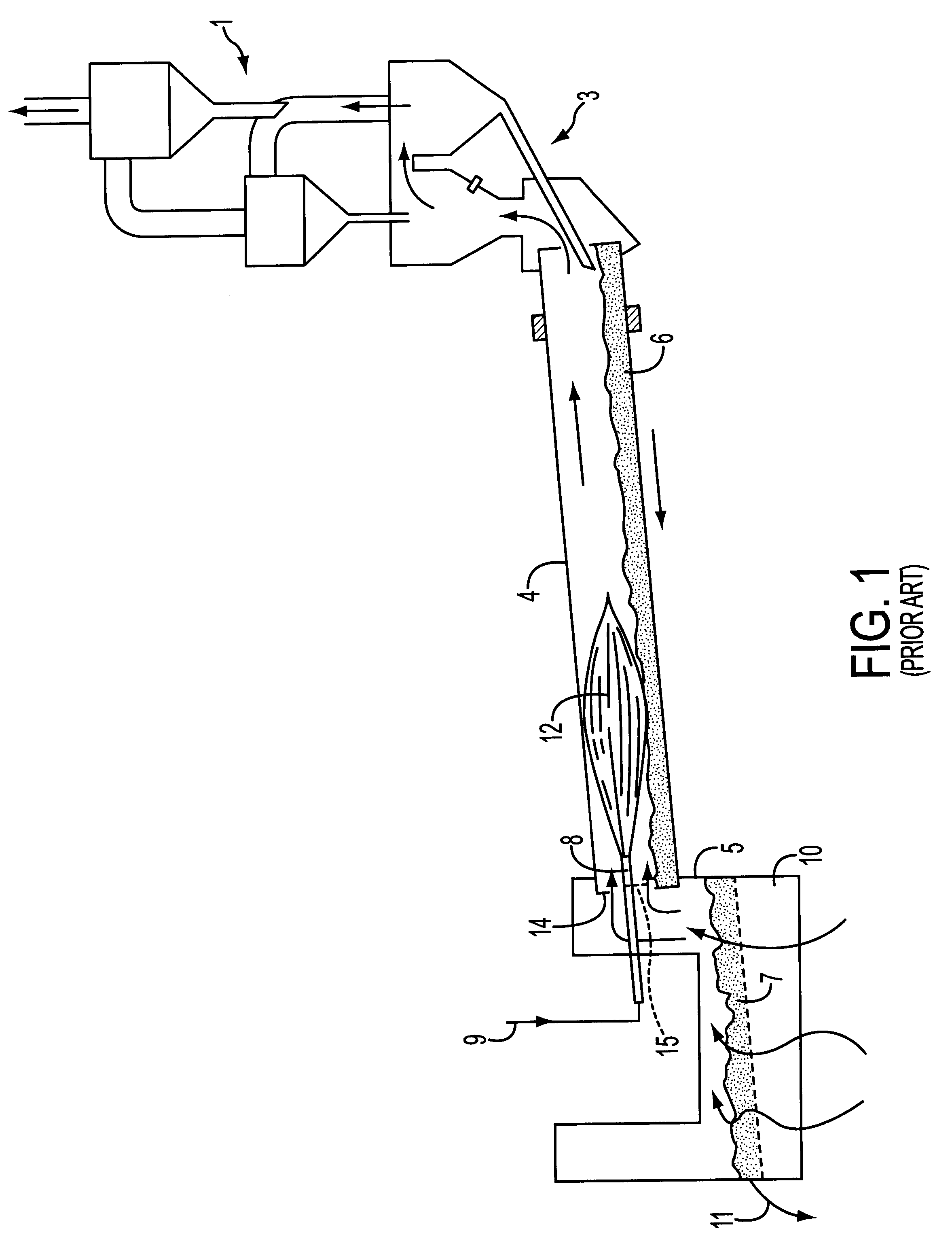
In FIG. 1, the green material coming from zone 1 is sent into the precalcining zone 3 (or, 10 according to a certain embodiment, a Lepol-type exchanger) in which the temperature of the green material progressively rises with the countercurrent of hot gases flowing from the left to the right in the figure.
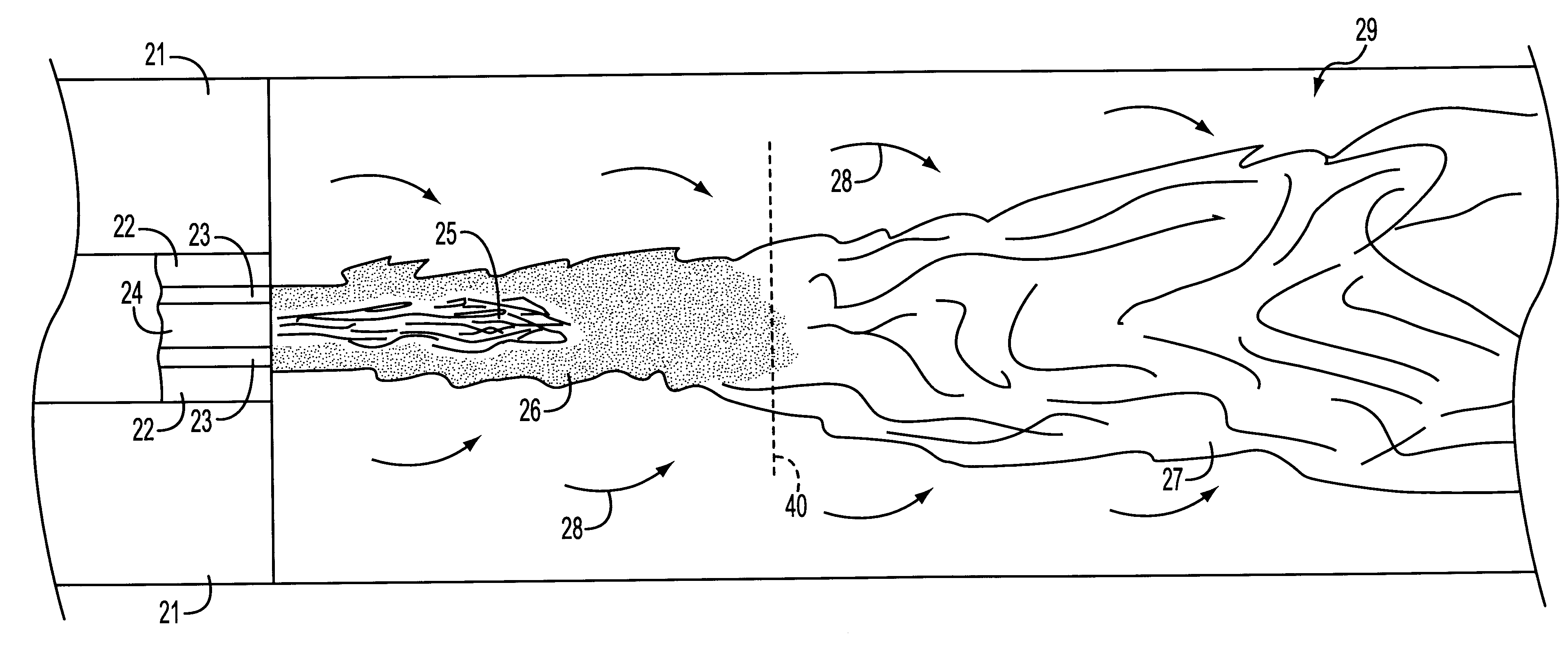
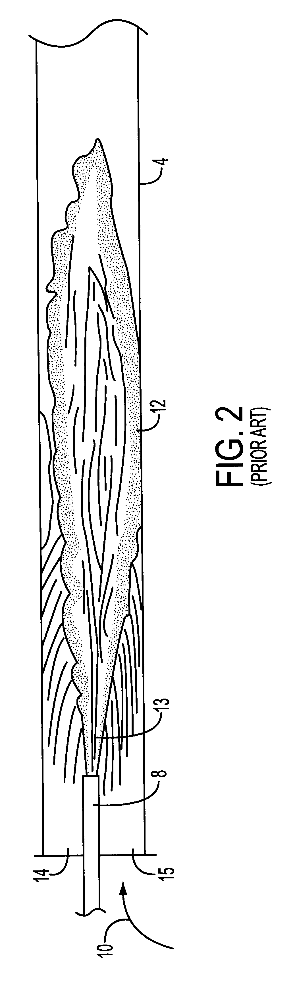
FIG. 2 shows a detailed view of the flame (12) shown in FIG. 1. In this figure, the same elements as those in the other figures bear the same reference numbers. The flame extends over a great length of the rotary kiln (4) and the beginning of the combustion starts effectively at a certain distance from the end of the burner (8), the noncombustion zone visible between the end of the burner and the beginning of the flame being shown by the zone (13). The primary air and the main fuel are injected into the burner, while the secondary air is injected along the sides (according to the prior art). The primary air is injected at a temperature of approximately 100.degree. C. the secondary air has a temperature often between 500 and 900.degree. C. while the temperature of the flame in its hottest part is at least about 1900.degree. C. The length of the flame in such a rotary kiln is typically from 4 to 7 times the diameter of the rotary kiln (4).
FIGS. 3A and 3B show, with the same reference numbers as in the previous figures, the flames of the prior art, in the case in which the ignition distance (D) shown by the zone (13) is correct in order to ensure good combustion, this distance (D) generally being less than 1 meter (FIG. 3A) while shown in FIG. 3B is typically a degraded flame, that is to say the zone. (13) extends over an unacceptable length D which is about 2 to 3 meters or more. Not only is this ignition distance too great but the position of the ignition, that is to say the end of the unignited zone may fluctuate greatly and there is a risk of flame detachment. Typically, the injection of poor-quality fuels into an existing flame of the prior art as described above leads to a degraded flame, as shown in this FIG. 3B, this being unacceptable both from the standpoint of the combustion and from the standpoint of the safety of the plant.
The next FIGS. (4, 5 and 6) show various embodiments of the invention. FIG. 4 shows a first solution according to the invention, in which the hot oxy-fuel flame is located around the jet of secondary fuel of poor quality, that is to say it surrounds the latter. The secondary fuel is injected (at 24), while the oxygen/first fuel mixture is injected around the secondary fuel through the concentric orifice (23) so as to create a flame sufficiently hot to preheat, as was described above, the poor-quality fuel injected through the orifice (24). As shown in the figure, the flame develops with, at the center in the upstream zone of the flame, a zone (25) in which the second fuel is preheated by contact with the generally hot oxy-fuel flame, which develops in the zone (26) around the poor-quality fuel, while a second, downstream combustion zone develops largely beyond the vertical line (40) shown in the figure, generally when approximately more than 90% of the oxidizer, i.e. the oxygen used in the hot flame (26), has already reacted with the first (generally high-quality) fuel to create the hot flame which preheats the second fuel. Downstream of the line (40), there is the second combustion zone of the flame resulting essentially from the combustion of the second (poor-quality) fuel with the surrounding air, i.e. the primary air injected through the annular cavity (22) and/or the so-called secondary air injected through the annular cavity (21), which air, as within the context of the prior art, has generally been preheated to a temperature of between 500 and 1000.degree. C. this preheating taking place in contact with the clinker formed in the rotary kiln, so as to cool the latter using air pumped from the outside at the surrounding temperature. The entire flame (29) therefore has a rear part upstream of the line (40), essentially formed by a short oxy-fuel flame which preheats the second fuel, and a downstream part (27) in which the main combustion according to the invention occurs, of the poor-quality fuel with air, which combustion may be carried out under correct conditions by the preheating, according to the invention, of the poor-quality fuel in the upstream part of the flame.
FIG. 5 shows another embodiment of the invention, in which the flame which heats the poor-quality fuel (25) is injected centrally in the injection system, while the poor-quality fuel to preheated surrounds this oxy-fuel flame injected through the orifice (23). The other elements remain similar to those described in FIG. 4 with the same operating principle, namely, in the upstream zone, preheating of the poor-quality fuel which thus reaches the downstream part generally with a temperature preferably greater than or equal to 1000.degree. C. thereby making it possible to burn quite correctly with the primary and/or secondary air emanating from the annular cavities (22) and/or (21).
According to one characteristic of the invention, the poor-quality second fuel, which must be preheated by the preferably oxygen/first fuel flame, will be injected into the latter or on the outside of the latter at a velocity which will preferably not exceed 50 meters/s and more preferably which will not exceed 20 meters/s. In general, it has been found that the injection velocities of this second fuel to be reheated, which are about 10 meters/s, were particularly suitable when the fuels are fuels having a low NCV or aqueous fuels, such as sludge from purification stations, etc.
Within the context of the present invention, it is not in fact precluded for it to be possible also to inject solid waste in addition to the second fuel, this solid waste, such as carpet waste or plastic waste, generally consisting of relatively coarse pieces and being injected at velocities which, in contrast, are high, for example about 200 meters/s, so as to be thrown as far as possible upstream of the zone for clinkering the clinker and so as then to be able to be pyrolyzed and thus to be associated with the formation of the clinker.
FIG. 6 shows an embodiment of the invention corresponding to a modification of an existing burner in a kiln (32). The entire system (31) comprises, in its lower part, the existing burner (32) and, in its upper part, the assembly added according to the process of the invention. In its lower part, the fuel, which optionally includes waste, especially solid waste, is injected through the orifice (34) pneumatically by means of the primary air, while the secondary air is injected into the annular pipe (33) so as to produce the combustion system according to the prior art. Placed above this combustion system, and more preferably on the same vertical axis, is a combustion system according to the invention in which the second fuel (35) to be preheated is located at the center of a flame injected via the annular cover (36) preferably consisting, as described above, of oxygen and a first fuel so as to preheat this second fuel. This second fuel preferably consists, as indicated above, of a pulverulent or liquid fuel which has to be preheated before being able to react, in the secondary combustion zone of the flame, with the secondary air, especially that which has not reacted with the flame (33-34). The elements of this flame (35-36) encounter the elements of the air/fuel flame by gravity. Of course, here again it is possible, according to one embodiment of the invention, to place the hot flame (36) at the center and the injection of second fuels (35) around this hot flame (36).

PUM

PropertyMeasurementUnit
Fraction0.21fraction
Fraction0.5fraction
Fraction0.98fraction
tensileMPa
Particle sizePa
strength10

Description & Claims & Application Information

We can also present the details of the Description, Claims and Application information to help users get a comprehensive understanding of the technical details of the patent, such as background art, summary of invention, brief description of drawings, description of embodiments, and other original content. On the other hand, users can also determine the specific scope of protection of the technology through the list of claims; as well as understand the changes in the life cycle of the technology with the presentation of the patent timeline. Login to view more.

Similar technology patents

Method of producing resin varnish for printing ink

ActiveUS6894096B2Easily produceRaise temperatureInksNatural resin chemical modificationSolventChemistry
Owner:HARIMA CHEM INC

Geothermal district heating power system

PendingUS20220259989A1Raise temperatureDistrict heating systemLighting and heating apparatusFossil fuelHeating power
Owner:ORMAT TECH INC

Classification and recommendation of technical efficacy words

Why Eureka
Try Eureka