Head tracker system

a head tracker and tracker technology, applied in the field of head tracker systems, can solve the problems of restricting the user's movement, unable to compensate for mechanical misalignment of the hmd, and limited accuracy of some of the systems

Inactive Publication Date: 2002-04-23
BAE SYSTEMS PLC
View PDF12 Cites 169 Cited by
  • Summary
  • Abstract
  • Description
  • Claims
  • Application Information

AI Technical Summary

Problems solved by technology

For example, early tracking systems used mechanical linkages between the helmet and the vehicle and, whilst such systems were relatively accurate, they were cumbersome, restricted the user's movement and posed particular problems during ejection from an aircraft.
These two qualities are often mutually exclusive and although advances in sensor technology, for example solid state gyroscopes, have increased the dynamic response of the tracker system, the accuracy of some of these systems is limited by drift over extended periods of operation.
Whilst initial boresighting ensures that the tracker system and HMD operate accurately at the commencement of operation, it cannot compensate for any mechanical misalignment of the HMD with respect to the helmet, nor for any drift in the tracker system.
Furthermore whilst the boresighting process may not be lengthy this can still be regarded as an unacceptable delay before the vehicle is operational.
At present HMDs do not achieve the accuracy of HUDs even when operating on the boresight axis due to the limited accuracy of the head tracker which is due in part to drift.
Moreover the distributed architecture of HMDs does not easily provide a high level of integrity, that is the assurance that it is providing accurate information.
However in the case of the head tracker there is no independent parallel path by which the accuracy of the tracker can be verified.

Method used


Image

  • Head tracker system
  • Head tracker system

Examples


Embodiment Construction

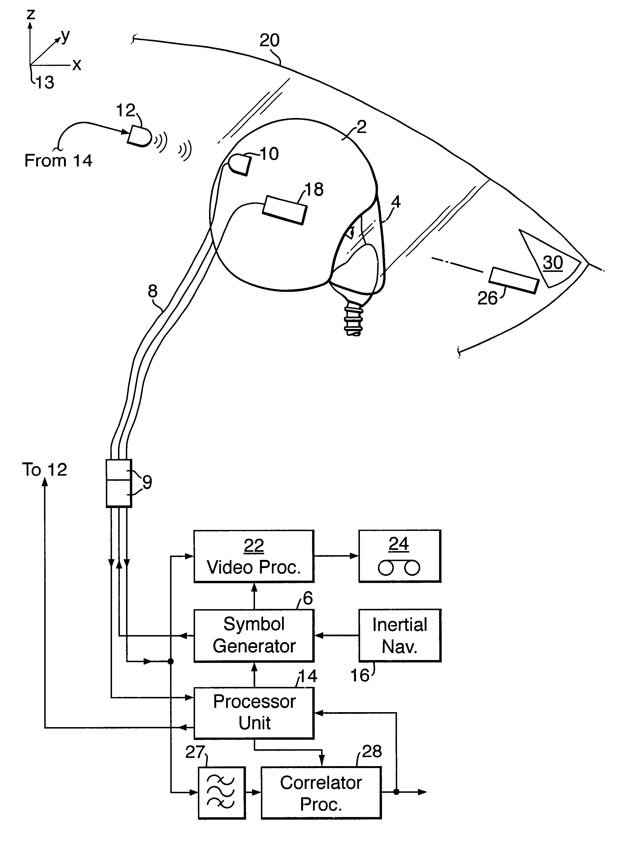
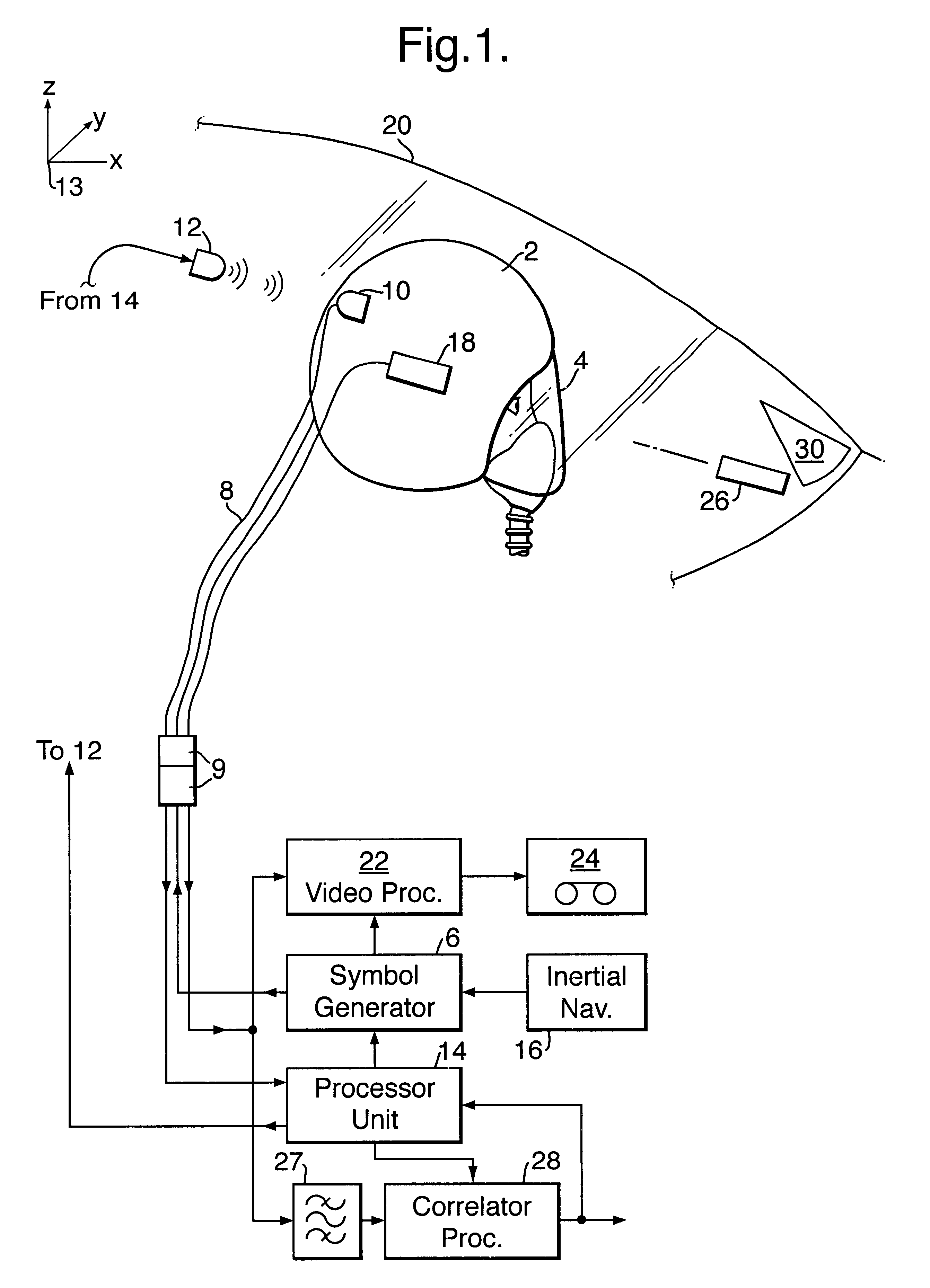
Referring to the drawing there is shown a helmet 2 which constitutes a head mounting for attachment to the head of a pilot, the helmet being provided with a visor 4. Internally the helmet 2 is provided with a helmet mounted display (HMD) device (not shown) which is arranged to project a display onto a partially reflective inner surface of the visor 4 or discrete eyepiece so that the display is superimposed upon at least part of the view seen by the pilot through the visor 4. As is known the symbology displayed on the HMD is generated by a symbol generator 6 which is located within the aircraft. The signals used to drive the HMD are passed to the helmet 2 along an umbilical cord 8 which is provided, in a known manner, with a quick release connector arrangement 9 fixed inside the cockpit.

The helmet 2 supports a sensor unit 10 which comprises part of a magnetic head tracker system in conjunction with a transmitter unit 12 which is secured to the cockpit canopy close to the helmet 2. Th...


PUM


Abstract

A head tracker system for determining a user's head orientation relative to a datum comprises: a head mounting, preferably a helmet (2), for attachment to the user's head and a sensor system (10,12) for sensing the orientation of the head mounting (2) relative and the datum. A distinguishable marking (26) is provided at a first known point fixed relative to the head mounting or a second known point fixed relative to the datum. At the other known point an optical sensor (18), preferably a video camera, is mounted. The system further comprises processing means (28) for determining when the marking is within the field of view of the optical sensor and the output of the processing means is used to correct for drift in the sensor system or to provide an independent verification that the system is functioning within preselected tolerances.

Description

1. Field of the InventionThis invention relates to a head tracker system and more especially, although not exclusively, to a head tracker system for use in an aircraft in which the pilot is provided with a helmet-mounted display.2. Discussion of Prior ArtHead tracker systems are well known and operate to determine a user's head orientation and position relative to a fixed datum. Originally these systems were developed for use in military aviation but have recently found applications in virtual reality systems.Since the earliest days of military aviation, pilots have not surprisingly preferred to navigate and aim weapons whilst looking up and out of the cockpit. This led to the evolution of the head-up display (HUD) which displays useful symbology which is appropriately referenced to the outside world (often termed "space stabilised"). HUDs typically have a viewing angle of thirty degrees or less and can consequently only be viewed when the pilot is looking in a generally forward dir...

Claims


Application Information

Patent Timeline
Patent Type & Authority Patents(United States)
IPC IPC(8): F41G3/22F41G3/00G06F3/00G06F3/01H04N5/64
CPCG06F3/012F41G3/225G06F3/0304
Inventor BARTLETT, CHRISTOPHER T
Owner BAE SYSTEMS PLC
Why Eureka
Try Eureka