
Device and process for the examination of cells using the patch-clamp method

Inactive Publication Date: 2002-04-30
FRAUNHOFER GESELLSCHAFT ZUR FOERDERUNG DER ANGEWANDTEN FORSCHUNG EV
View PDF2 Cites 33 Cited by
  • Summary
  • Abstract
  • Description
  • Claims
  • Application Information

AI Technical Summary

Benefits of technology

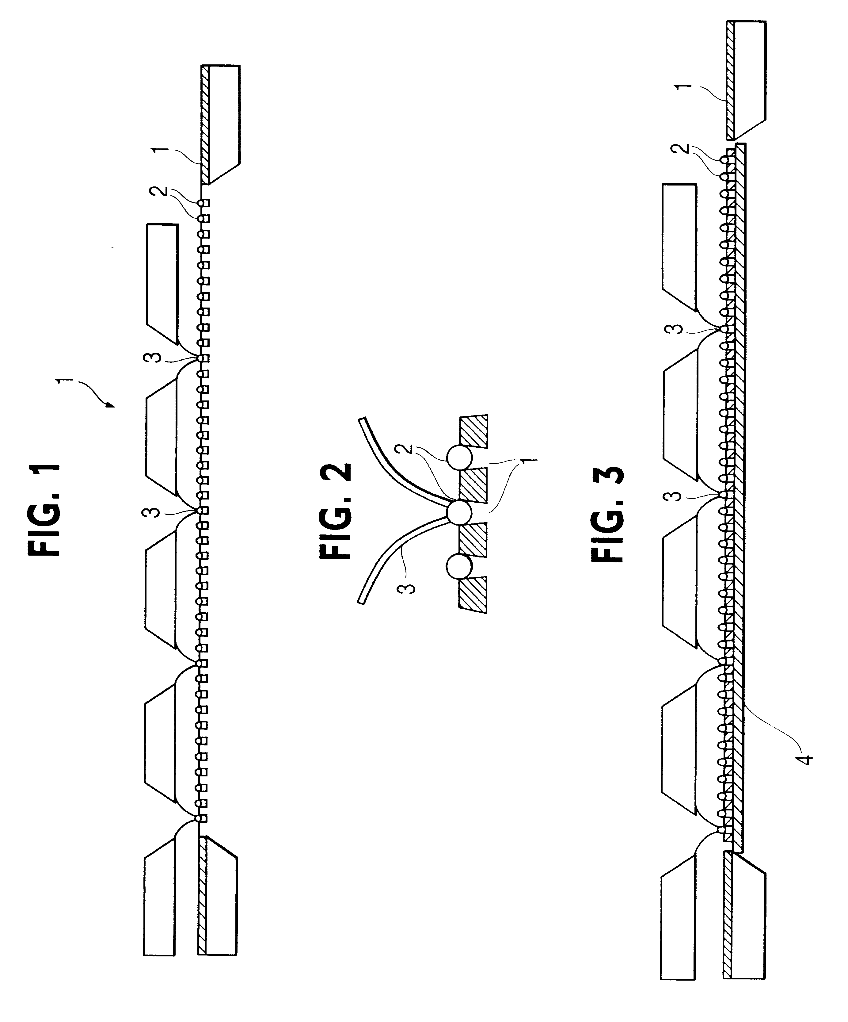
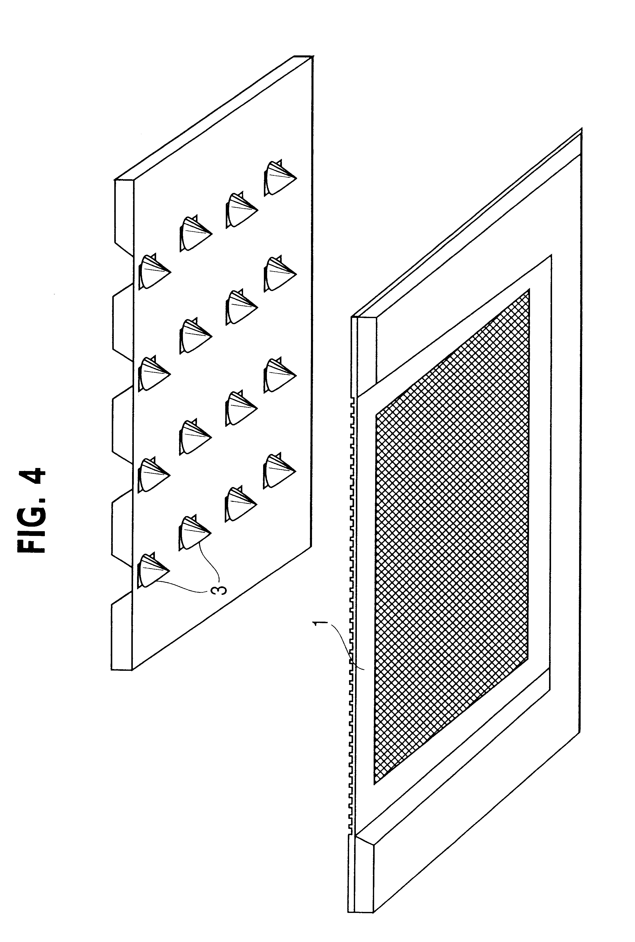
The systematic spatial arrangement of both the micro-cuvettes for the reception of the cells and the micro-pipettes permits for the first time automation of the patch-clamp method and thus conducting the patch-clamp method inexpensively and quickly. The to-be examined neurons are received by a plane arrangement of the micro-cuvettes, usually a substrate with uniformly distributed recesses in its surface, and in this manner retained in exactly determinable positions. With exact positioning, a plane arrangement of micro-pipettes in relation to the arrangement of the cells located in micro-cuvettes permits conducting a multiplicity of single measurements simultaneously, which hitherto could only be conducted successively and simultaneous observation with a microscope. The micro-pipettes relative to the micro-cuvettes can be arranged in an extremely confined space and permit in this manner the construction of very compact measuring devices. The cuvettes and pipettes are preferably uniformly distributed on the provided areas, i.e. with fixed spacing in relation to each other with the cuvettes and pipettes forming an uniform grid. In practice, the exact design of the grid will be dependent on the size and shape of the micro-pipettes and the micro-cuvettes.
In a simplest case of an uniform arrangement, the distance between adjacent micro-cuvettes corresponds to an integral fraction of the distance to the micro-pipettes, which are larger than the micro-cuvettes. A substantially greater number of cells can be simultaneously received than is the case with an arrangement of an equal number of cuvettes as pipettes. The number of simultaneous measurements is only limited by the size of the micro-pipettes respectively and by the size of the areas provided for them. In order to examine all the cells located in the micro-cuvettes, the corresponding preferred embodiment of the process provides that the multiplicity of the micro-pipettes is offset relative to the cell arrangement and a multiplicity of arranged cells is repeatedly examined. In this manner, the multiplicity measurement is repeated in short intervals without needing to intermittently replace the cells, leading to an additional increase in the throughput.
Another embodiment of the present invention provides a micro-motor for positioning and / or for offsetting the arrangement of micro-cuvettes and the arrangement of micro-pipettes. The micro-motor for lowering the micro-pipette arrangement onto the micro-pipette arrangement and for lateral reciprocal movement ensures, with the aid of present day precision mechanics and micro-technology, pinpoint contacting of neurons and pipettes, thereby permitting with the present invention for the first time the examination of a multiplicity of cells.
Another embodiment of the invention provides a cell feed device and or a rinsing device for removing the cells, which leads to further automation of the measurements and thereby to further saving of time, in particular, in the case of multiple measuring, which exceeds the reception capacity of the group of cuvettes.
Another embodiment of the invention provides a filter on the rear side of the arrangement of the micro-cuvettes. Rinsing the cuvette arrangement from the rear side is recommended, because the to-be-examined cells are introduced into the micro-cuvettes from the side facing the pipette arrangement and the micro-cuvettes are preferably widened conically in the direction of the pipettes. In this case, a filter is advantageous in order to prevent blockage of the micro-cuvette by the small particles.

Problems solved by technology

Although the patch-clamp method has become a state of the art measurement since its introduction in neuroscience, it is extremely sophisticated and hitherto requires microscopic control of the measure performed on the to-be-examined cell.
A drawback is primarily that this process requires considerable skill and sensitivity of the operator for handling individual nerve cells.
Due to the manual handling of the individual cells, the patch-clamp method has hitherto involved considerable consumption of time.
In particular, in the examination of a multiplicity of cells, this drawback is serious because the cells are spatially randomly distributed following their isolation from the tissue and for this reason can only be obtained, placed and examined in succession.

Method used


Image

  • Device and process for the examination of cells using the patch-clamp method
  • Device and process for the examination of cells using the patch-clamp method
  • Device and process for the examination of cells using the patch-clamp method

Examples


Embodiment Construction

The present invention provides a device and a process with which a multiplicity of cells can be simultaneously examined using the patch clamp method, to automate cell examination in such a manner that microscope control is obviated. Furthermore, the examination of a multiplicity of cells on the smallest possible space should become possible and finally the time consumed for patch-clamp measuring is drastically minimized.

According to the present invention, the problems of the prior art are solved with a device having a plane arrangement of a first number of micro-cuvettes for receiving cells and having a plane arrangement of a second number of micro-pipettes which can be positioned relative to the plane arrangement of micro-cuvettes in order to simultaneously examine a multiplicity of cells located in the micro-cuvettes. Measuring the bio-electric signals occurs using the patch-damp method.

Furthermore, the problems of the prior art are solved according to the present invention by mea...


PUM


Abstract

Disclosed is a device and a process for examining cells using the patch-clamp method. A plane arrangement is used of a first number of micro-cuvettes for receiving cells and a plane arrangement of a second number of micro-pipettes which can be positioned in relation to the plane arrangement of micro-cuvettes in such a manner that a multiplicity of cells located in the micro-curvettes can be examined simultaneously.

Description

The present invention relates to a device and a process for the examination of cells using the patch-clamp method. Furthermore, the subject-matter of the present invention is the use of a, as such known, device for measuring bioelectric signals for examining cells.STATE OF THE ARTThe patch-clamp method is a process for measuring bio-electric signals, namely the electric potential inside a cell and the current created by ionic transport processes, the so-called ion channels, running through a cell membrane.This process permits even measuring the current running through a cell membrane separately for a specific ion channel and in this manner to obtain information about how the cell membrane functions. Measurements with the patch-clamp method are conducted in neuroscience to investigate the effects of pharmaceuticals and chemotherapy on the action of the ion channels.Devices for measuring bio-electric signals are known from DE 38 05 808 Al and U.S. Pat. Nos. 4,599,315, 5,229,163 and 5,...

Claims


Application Information

Patent Timeline
IPC IPC(8): C12M1/34G01N33/487
CPCG01N33/48728
Inventor MEYER, JOERG UWE
Owner FRAUNHOFER GESELLSCHAFT ZUR FOERDERUNG DER ANGEWANDTEN FORSCHUNG EV
Learn More