Turbocharger housing with exhaust gas recycling

a technology of exhaust gas recycling and turbocharger, which is applied in the direction of non-fuel substance addition to fuel, machines/engines, mechanical apparatus, etc., can solve the problems of bulky wastegates and easy leakage of all associated connections, and achieve the effect of convenient assembly to a vehicl

Inactive Publication Date: 2002-05-07
SCANIA CV AB
View PDF12 Cites 40 Cited by
  • Summary
  • Abstract
  • Description
  • Claims
  • Application Information

AI Technical Summary

Benefits of technology

Although a turbocharger housing according to the invention is more complicated than a conventional turbocharger housing, since the whole is supplied as a single unit it is easier to assemble to a

Problems solved by technology

The EGR valve, and wastegate are bulky and all the

Method used


Image

  • Turbocharger housing with exhaust gas recycling
  • Turbocharger housing with exhaust gas recycling

Examples


Embodiment Construction

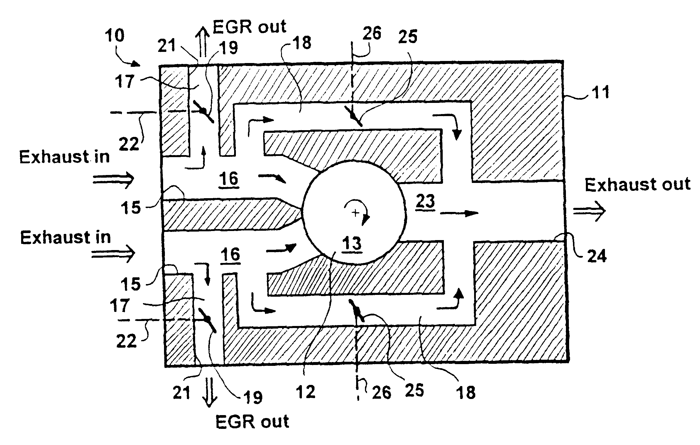
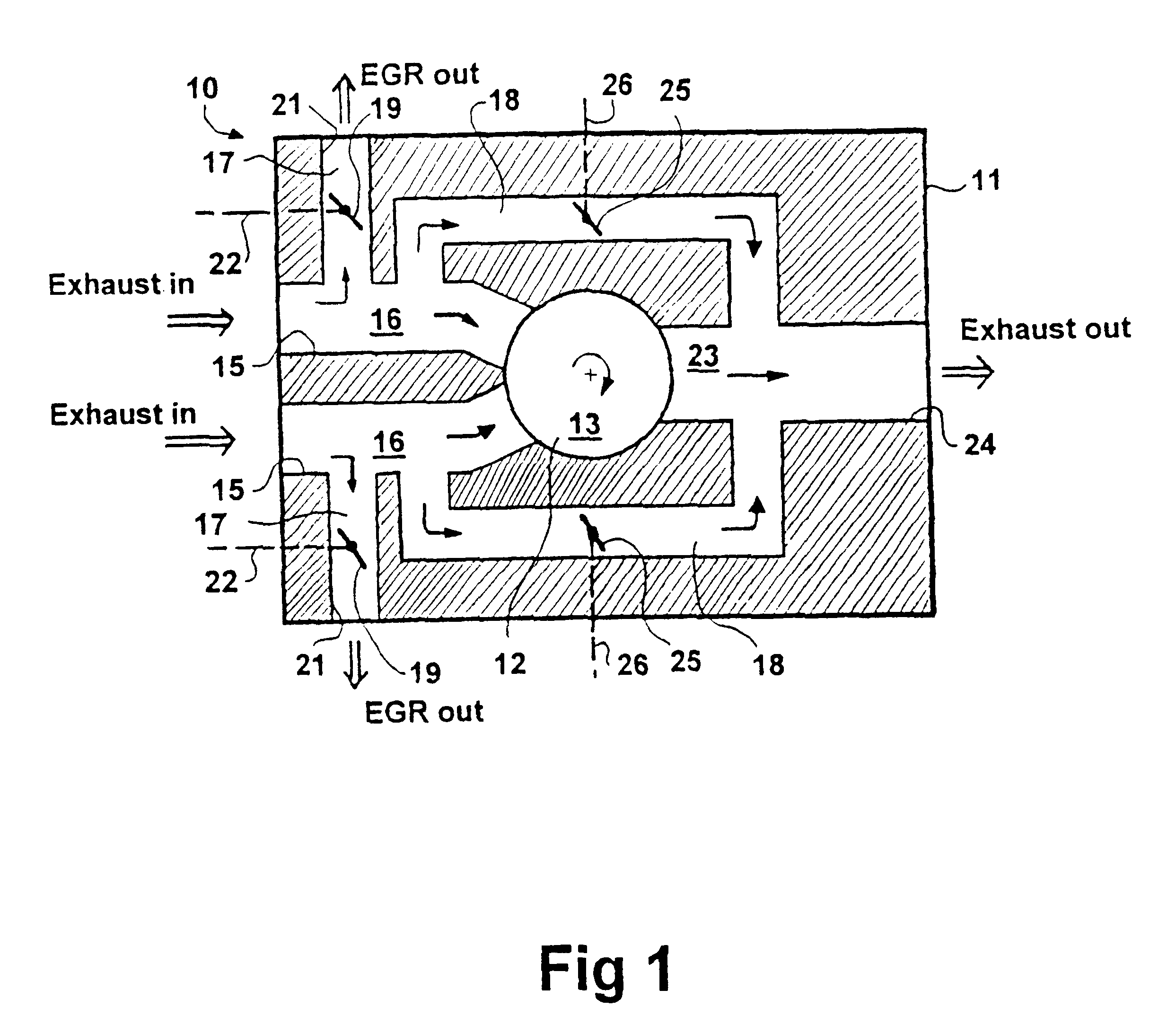
With reference to the accompanying schematic drawing FIG. 1, a turbocharger 10 has a housing 11 of a suitable material such as a shaped and machined metal, typically steel or iron. The housing 11 includes a turbine chamber 12 housing a turbine 13 which is mounted on a shaft (not shown) connected to a compressor, as is well known for turbochargers.

The turbocharger in use is connected to a pair of exhaust manifolds as might be used in a direct injection diesel engine arranged in a V configuration. Alternatively the pair of exhaust manifolds might be connected to two different sets of cylinders as might be used in an engine with the cylinders arranged in line.

The housing 11 has a respective exhaust inlet port 15 for each engine exhaust manifold. In this case there are two inlet ports 15 each for connection to one of the two exhaust manifolds. Each inlet port opens into a respective passageway 16 connected to the turbine chamber 12.

Each passageway 16 also connects to two further passage...


PUM


Abstract

A turbocharger for an internal combustion engine and which has a housing with a turbine housed in a chamber in the housing, and driven by exhaust gases from the engine. The turbocharger has an integral EGR valve and wastegate.

Description

FIELDThis invention relates to turbochargers of the type used in cooperation with internal combustion engines, mainly compression ignition engines. In particular the invention relates to a turbocharger housing having a chamber for a turbine and having passageways in the housing for passage of exhaust gas and relates to a turbocharger which includes these elements as well as a wastegate and an EGR valve.A turbocharger has a compressor located in the air intake system of an internal combustion engine in order to increase the amount of air and thereby also the fuel delivered to a combustion chamber to increase power output from an engine. The compressor is driven by a turbine located in the exhaust gas outlet and connected to the compressor by a shaft.This has two advantages: 1) the engine is more efficient because it utilizes energy recovered from the exhaust gas flow and 2) a smaller engine can be made to produce a given power output.The power available to drive the compressor is a n...

Claims


Application Information

Patent Timeline
IPC IPC(8): F02B37/18F02M25/07F02B47/00F02B47/08F02B39/00
CPCF02B37/025F02B37/18F02B47/08F02M25/0707F02M25/0778F02M25/0719Y02T10/144F02M25/0744Y02T10/121F02M26/05F02M26/16F02M26/38F02M26/58Y02T10/12
Inventor M.ANG.RDBERG, JORGEN
Owner SCANIA CV AB
Why Eureka
Try Eureka