Valve timing control device

a timing control and valve technology, applied in valve arrangements, machines/engines, mechanical equipment, etc., can solve the problems of affecting the discharge speed of backward pressure, so as to reduce the number of parts of the device, facilitate assembly, and reduce manufacturing costs

Inactive Publication Date: 2002-05-07
MITSUBISHI ELECTRIC CORP
View PDF7 Cites 15 Cited by
  • Summary
  • Abstract
  • Description
  • Claims
  • Application Information

AI Technical Summary

Benefits of technology

The variable throttle mechanism may close the discharge hole continuously and variably. In this way, since the opening area of the discharge hole on releasing the lock due to the lock member can be throttled continuously and variably, a releasing speed can be changed continuously.
The variable throttle mechanism may have a biasing member for biasing the sliding member in a direction of opening the discharge hole on locking the lock due to the lock member. In this way, since the sliding member, which throttles the opening area of the discharge hole on locking due to the lock member until now, can be slid in a direction of controlling the opening area of the discharge hole at the maximum, the engagement due to the lock member can be performed at the same speed as the conventional device.
The variable throttle mechanism may include a throttle rod integrated with the lock member, the throttle rod closing the discharge hole on releasing the lock due to the lock member and opening the discharge hole on locking due to the lock member. In this way, with the device, the discharge hole can be closed on releasing the lock due to the lock member and can be opened on locking. Moreover, since the number of parts of the device can be reduced, it is possible to reduce manufacturing costs and facilitate assembly.
The throttle rod may slide coaxially on the sliding axis of the lock member to close the discharge hole on releasing the lock due to the lock member and may slide coaxially on the sliding axis of the lock member to open the discharge hole on locking due to the lock member. In this way, the discharge hole can be closed effectively on releasing the lock due to the lock member and opened effectively on locking.
The variable throttle mechanism may close the discharge hole in a stepwise manner. In this way, the opening area of the discharge hole can be throttled in a stepwise manner on releasing the lock due to the lock member, the releasing speed can be changed in a stepwise manner.

Problems solved by technology

In this way, since the first and second rotors undergo repetitive contact and separation as a result of the vibration, beat noise (abnormal noise) necessarily results.
However, the following problems result from the above structure for a conventional valve timing control device.
Since the first and second rotors repeat contact and separation therebetween, beat noise (abnormal noise) necessarily results.
In this way, since the opening area of the discharge hole can be throttled on releasing the lock due to the lock member, a discharge speed of the backward pressure can delay considerably as compared with the conventional device.
Moreover, with a state of rising a hydraulic pressure on starting the engine, a release operation due to the lock member cannot be performed promptly.

Method used


Image

  • Valve timing control device
  • Valve timing control device
  • Valve timing control device

Examples


embodiment 1

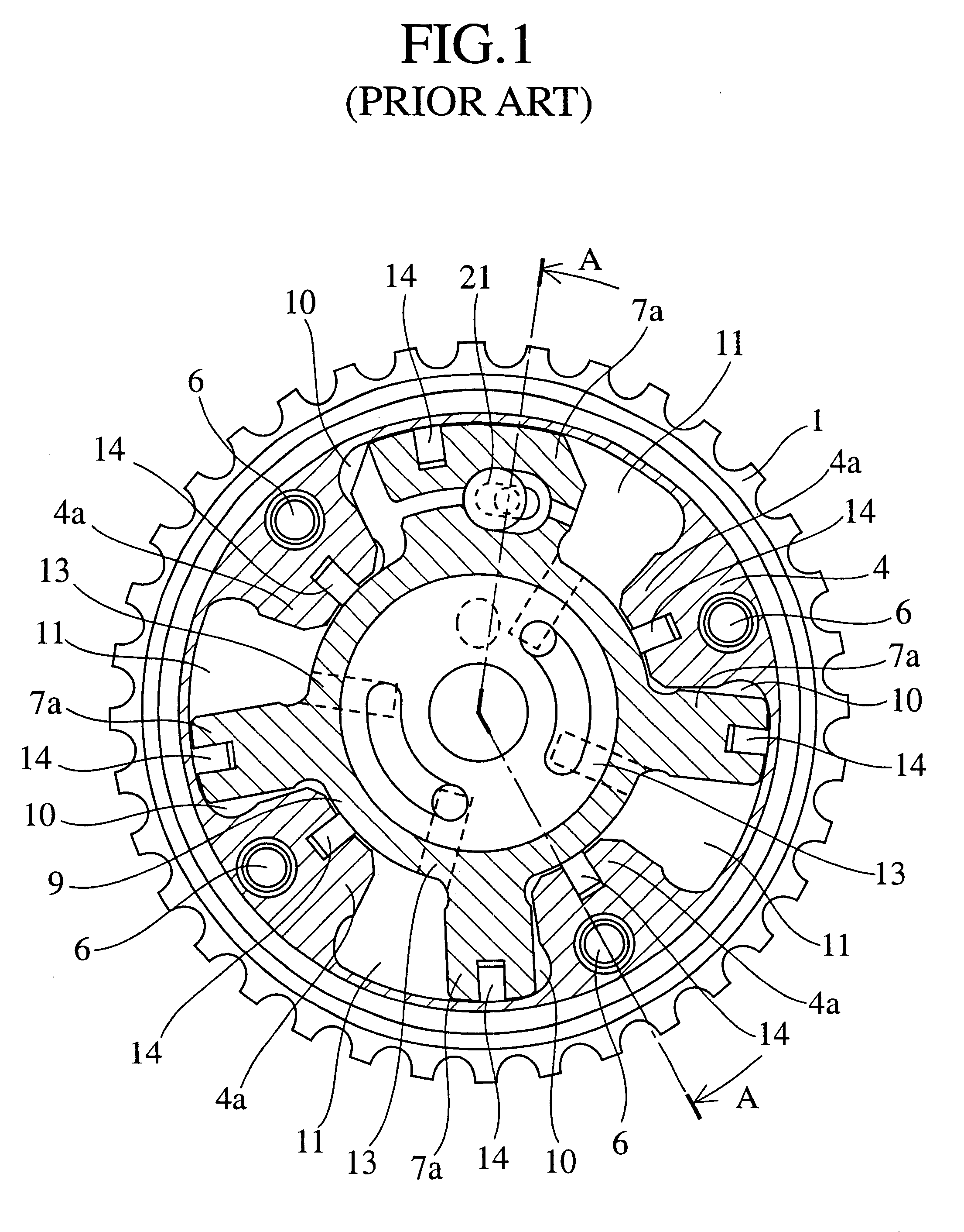
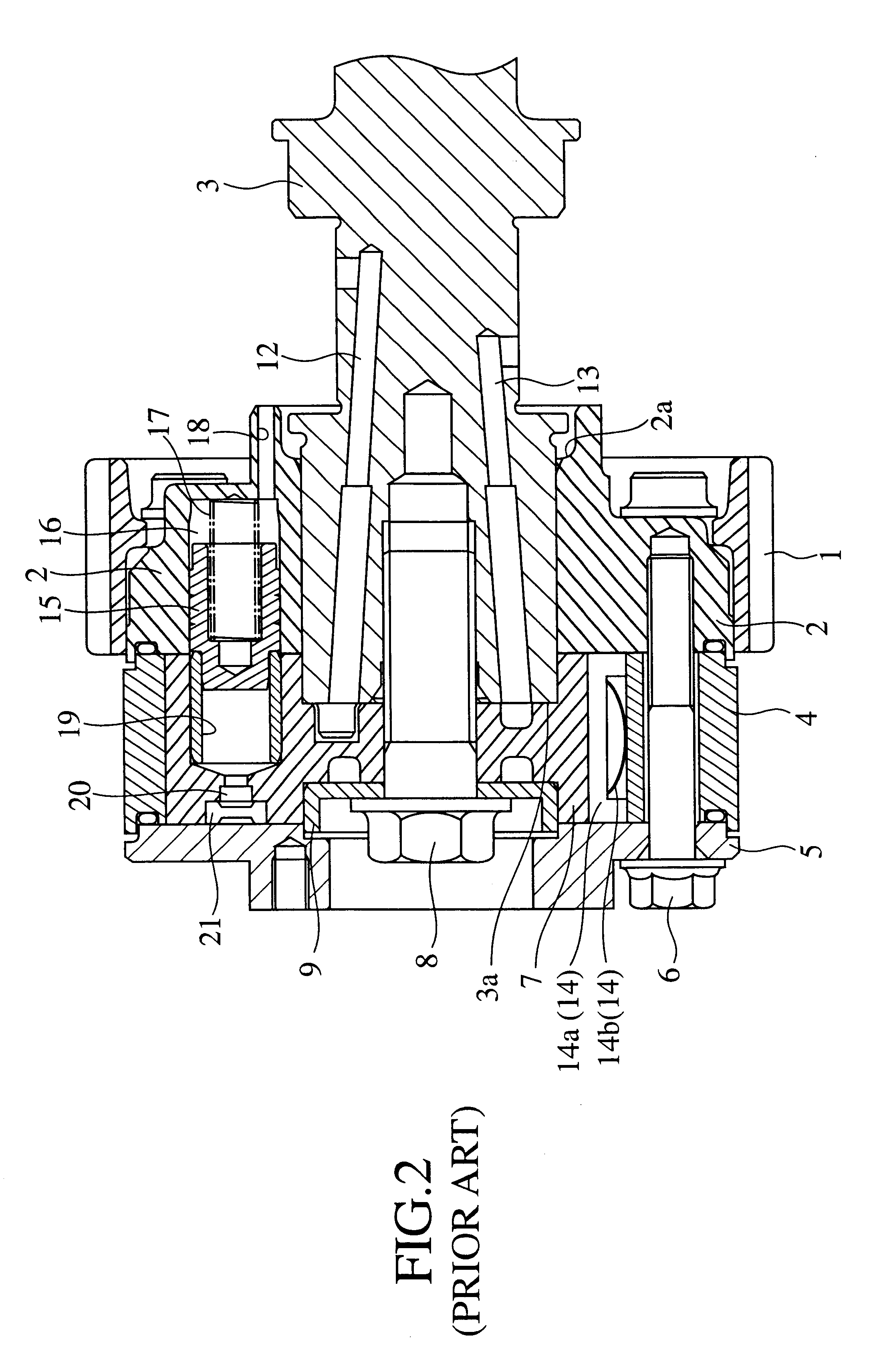
FIG. 4A to FIG. 4C are cross sectional views of variable throttle mechanism resulting from operation of a lock member in a valve timing control device as embodiment 1 according to the present invention. In the drawings since the common numerals denote common elements in the conventional structure of FIG. 1 to FIG. 3C, the description of such parts is omitted. Moreover, in the explanation of the first rotor, a side, close to the second rotor, of the first rotor is defined as a forward side, and the other side, away from the second rotor, of the first rotor is defined as a backward side. This definition is the same as the embodiments 2 and 3 will be explained hereafter.

The backward pressure chamber 16 in the embodiment 1 includes a major diameter section 16a formed at a front or shallow side in the chamber 16 and a minor diameter section 16b formed at a back or deep side in the chamber 16. A cylindrical holder 22 is press-fitted to the major diameter section 16a, the holder 22 having ...

embodiment 2

FIG. 5A to FIG. 5 are cross sectional views of variable throttle mechanism resulting from operation of a lock member in a valve timing control device as embodiment 2 according to in the present invention. In the drawings, since the common numerals denote common elements in the embodiment 1, the description of such parts is omitted.

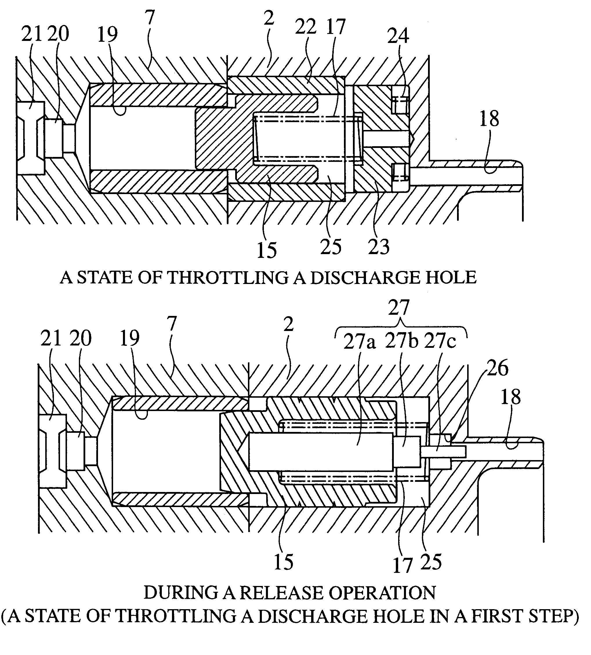
The embodiment 2 is characterized in that a tier-providing opening 26 is arranged at a central portion of the rear wall face 16c of the backward pressure chamber 16 and that the discharge hole 18 is formed in the tier-providing opening 26 to be coaxial to the lock pin 15 and the backward pressure chamber 16. Moreover, the embodiment 2 is characterized in that a throttle rod (variable throttle mechanism) 27 having a cantilever shape is formed so as to extend from the bottom of the concave portion 15c of the lock pin 15 in a backward direction. The throttle rod 27 includes a major diameter section 27a arranged in the concave portion 15c of the lock pin 15, a...

embodiment 3

FIG. 6A to FIG. 6C are cross sectional views of variable throttle mechanism resulting from operation of a lock member in a valve timing control device as embodiment 3 according to the present invention. In the drawings, since the common numerals denote common elements in the embodiment 1 and so on, the description of such parts is omitted.

The embodiment 3 is characterized in that the discharge hole 18 is arranged at a position apart from the central axis of the backward pressure chamber 16 and that a cylindrical sliding member 28 is arranged within the tier-providing opening 26. The sliding member 28 has a perforation hole 28a formed at the central portion thereof without directly communicating with the discharge hole 18. A length of the sliding member 28 in the sliding direction is set to be shorter than a length of the tier-providing opening 26 in the same direction. A toroidal plate 29 is arranged at the rear wall face 16c of the backward pressure chamber 16. The inner diameter o...


PUM


Abstract

A valve timing control device has a hydraulic pressure supply passage for supplying a hydraulic pressure used for releasing lock due to the lock member. If a hydraulic pressure applied to the hydraulic pressure supply passage reaches a required pressure, a hydraulic pressure subjected to a major diameter section of the lock member is larger than the sum total of the biasing force of two biasing members. Thus, the lock member is returned in a direction of releasing the lock due to the lock member. The sliding member is moved backward while the lock member is also moved backward. The stroke of the sliding member is extremely shorter than that of the lock pin. With a locked state of leaving the engagement of a minor diameter section of the lock member with an engagement hole, a rear end face of a minor diameter section of the sliding member abuts with a rear wall face 16c of a backward pressure chamber. Thus, it is difficult that a backward pressure space defined between the lock member and the sliding member communicates with a discharge hole. Since the opening area of the discharge hole substantially is throttled, a speed of discharging the backward pressure is considerably delayed.

Description

1. Field of the InventionThe present invention relates to a valve timing control device,for modifying the-opening and closing timing of the intake and exhaust valves in an internal-combustion engine (hereafter, ref erred as an engine) according to any operating condition.2. Description of the Prior ArtConventional valve timing control devices of various structures,are proposed as disclosed in JP-A-1998 / 159519, JP-A1998 / 159520 and JP-A-1999 / 294120, for example.FIG. 1 is a lateral cross sectional view of an internal construction of the) conventional vane-type valve timing control device. FIG. 2 is a longitudinal cross sectional view taken along lines A-A of FIG. 1. FIG. 3A and FIG. 3B are enlarged cross sectional views of a lock member in the valve timing control device of FIG. 2, FIG. 3A showing a locked state, and FIG. 3B showing a released state. In the drawings, reference numeral 1 denotes a pulley which connects with, a crankshaft (not shown) of the engine through chains (not sho...

Claims


Application Information

Patent Timeline
Patent Type & Authority Patents(United States)
IPC IPC(8): F01L1/344F01L1/34
CPCF01L1/3442
Inventor FUKUHARA, KATSUYUKIKINUGAWA, HIROYUKI
Owner MITSUBISHI ELECTRIC CORP
Why Eureka
Try Eureka