Moreover, because of the difficulties associated with their delivery and installation, and the criticality of their telecommunication function, submarine optical repeaters and branching stations are typically designed to have relatively long, and maintenance-free operating lives.
However, some devices require that more than one independent variable be changed simultaneously, resulting in a multidimensional nature to the measurement data.
Yet, the data structures of the known automated testing systems are incapable of handling
multidimensional data.
Thus, there is little
standardization among test scripts or their data structures, and therefore modifying a
test script, particularly an older one for which the original
programmer is unavailable to assist, can be a challenging endeavor.
Moreover, in the known automated testing systems, because the validation or limit checking routines are integral to the test scripts, measurement data can only be checked at the time of testing.
However, the known automated testing systems do not provide a means for adjusting the limits, but instead expect the limits provided to the automated testing
system to be adjusted for measurement error beforehand.
Yet the error for a measurement can vary from one batch to another, and from one independent variable value to another, so a
global change to the limits would not suffice.
Known automated testing systems are unable to check measurement data against non-numeric limits.
However, because the known automated testing systems do not allow non-
numeric data to be checked against non-numeric limits, the information provided by these instruments must be converted by the operator into a
numeric value before entry and limit-checking.
This conversion process can be time-consuming and error-prone.
Known automated testing systems do not allow for this measurement error, but rather expect the fixed limits to be adjusted to account for measurement error.
Typically, the error term for a measurement can vary from
test set to
test set and from test condition to test condition, so a
global change to the limits would not suffice.
The only limitation is that the guard-band value can not be dependent on any of the independent variables used for the test.
No attempt was made to
handle multi-dimensional data.
Known automated testing systems do not allow for this measurement error, but rather expect the fixed limits to be adjusted to account for measurement error.
Typically, the error term for a measurement can vary from
test set to test set and from test condition to test condition, so a
global change to the limits would not suffice.
The only limitation is that the guard-band value can not be dependent on any of the independent variables used for the test.
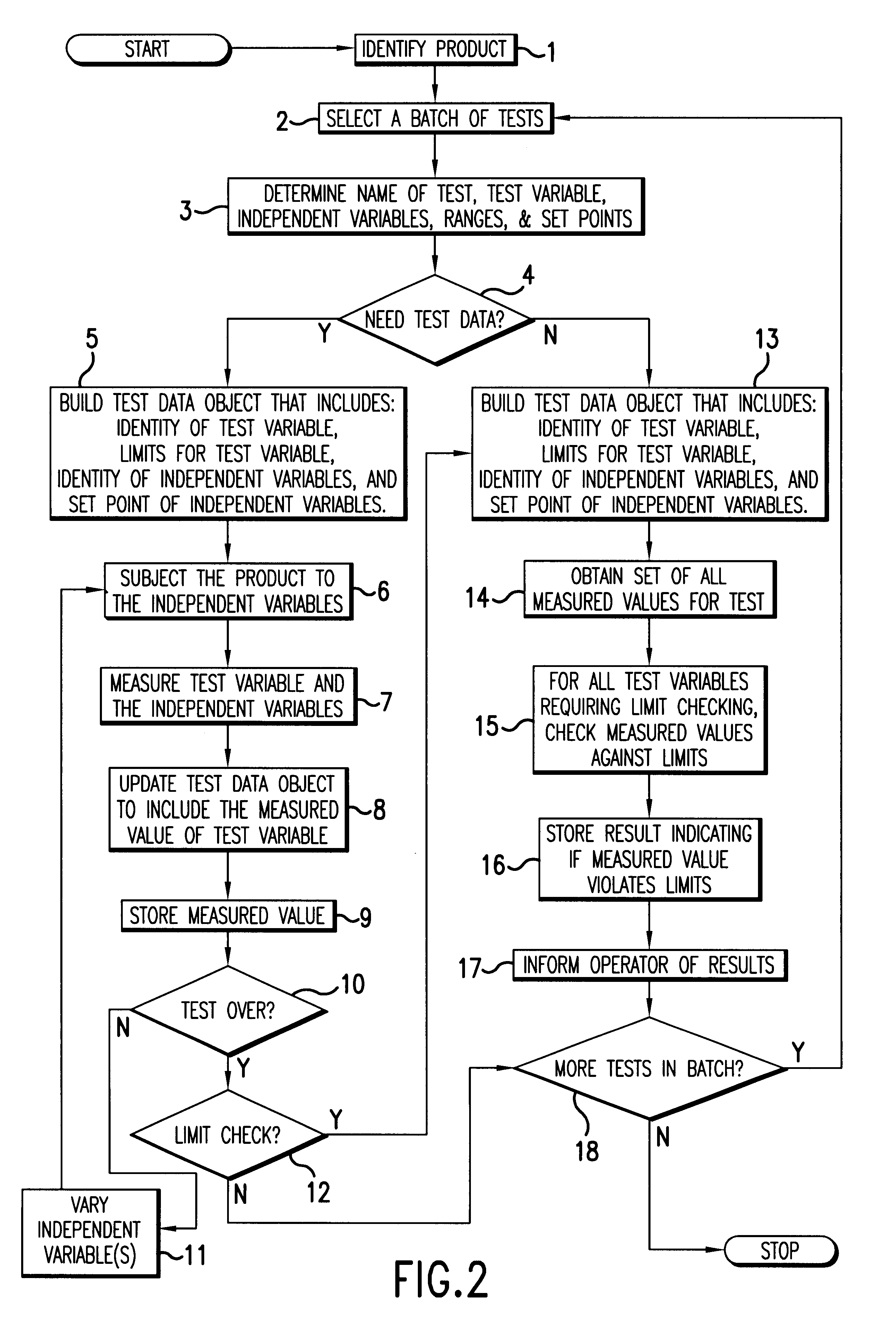
If some tests fail, the batch may continue while, for other tests, failure may cause the batch to abort.
As such these are inseparable from the raw measurement data.
The test limits however, do not have any
impact on the measurement process.
The test limits however, have no effect on the measurement process and can be therefore subject to manipulation in
software after the fact.
In the past, it has proven difficult to repeat a user's set of selections that produced a failure.
Also, cases have been encountered where the user claims that there is a
software error, when in fact, they simply made an incorrect menu selection.
Unfortunately, if the exception is recognized in a lower level procedure deep down the
call stack, there may not be enough information to determine the cause of the problem.
When an error condition is recognized, an error will be thrown and caught by the routine's local error handler.

