Air filter assembly having non-cylindrical filter elements, for filtering air with particulate matter

a technology of air filter and filter element, which is applied in the direction of separation process, filtration separation, transportation and packaging, etc., can solve the problems of often encountering particulate matter suspended in the atmosphere, using non-cylindrical filter elements, etc., and achieves the effect of increasing the amount of filtration media, increasing airflow, and increasing dust laden airflow

Inactive Publication Date: 2002-05-14
DONALDSON CO INC
View PDF31 Cites 73 Cited by
  • Summary
  • Abstract
  • Description
  • Claims
  • Application Information

AI Technical Summary

Benefits of technology

The construction and arrangement of the disclosed air filter assembly helps to overcome the problems of the prior art. In particular, in one embodiment, the structure and arrangement of the assembly of the present disclosure enables the processing of 25% more dust laden airflow compared to conventional systems. In preferred systems, the assembly of the present disclosure results in a dust laden airflow increase greater than 25% without an increase in the geometric size of the filter housing apparatus or the number of filter cartridges required. The present design provides this 25% volume increase, preferably greater than 25% increase, by maintaining the amount of filtration media available for filtering the dirty air rather than increasing the amount of filtration media. In another embodiment, the assembly of the present disclosure results in an airflow increase greater than 25% by decreasing the amount of filtration media available. Also, the structure and arrangement of the air filter assembly provides more efficient filter retention / sealing, filter housing apparatus manufacturing, and filter handling.

Problems solved by technology

Many industries often encounter particulate matter suspended in the atmosphere.
Unfortunately, each of these conventional designs which utilize non-cylindrical filter elements has its disadvantages and drawbacks.

Method used


Image

  • Air filter assembly having non-cylindrical filter elements, for filtering air with particulate matter
  • Air filter assembly having non-cylindrical filter elements, for filtering air with particulate matter
  • Air filter assembly having non-cylindrical filter elements, for filtering air with particulate matter

Examples


Embodiment Construction

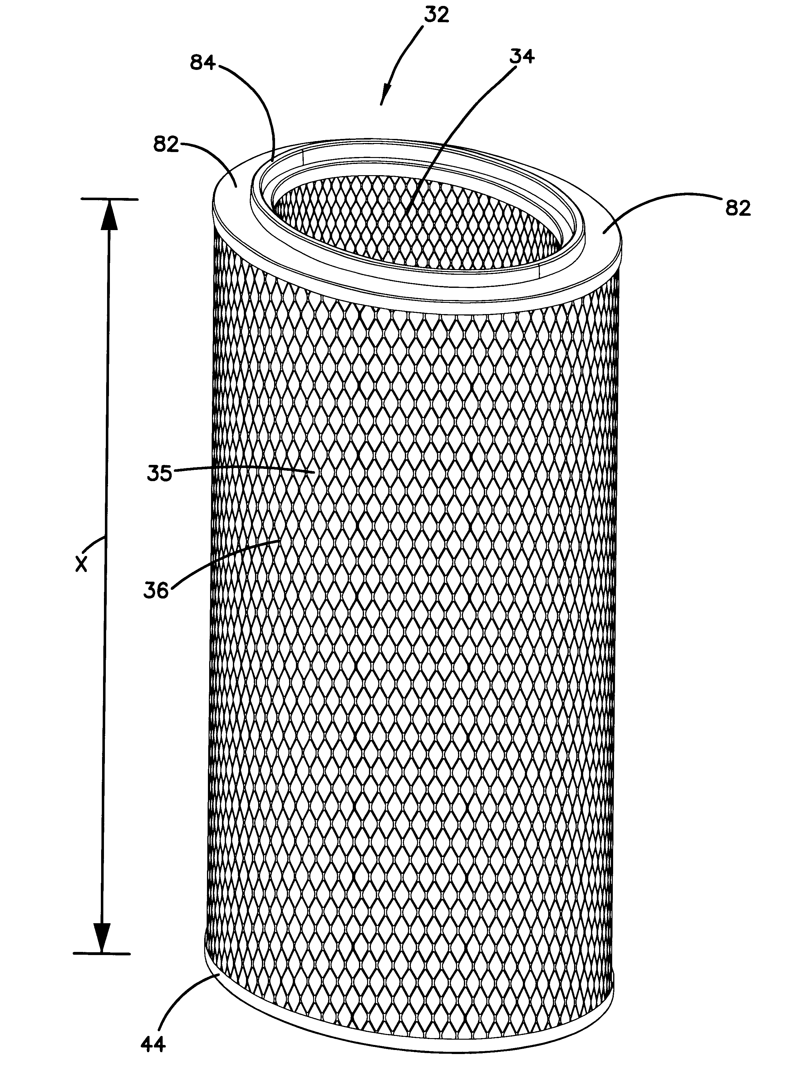
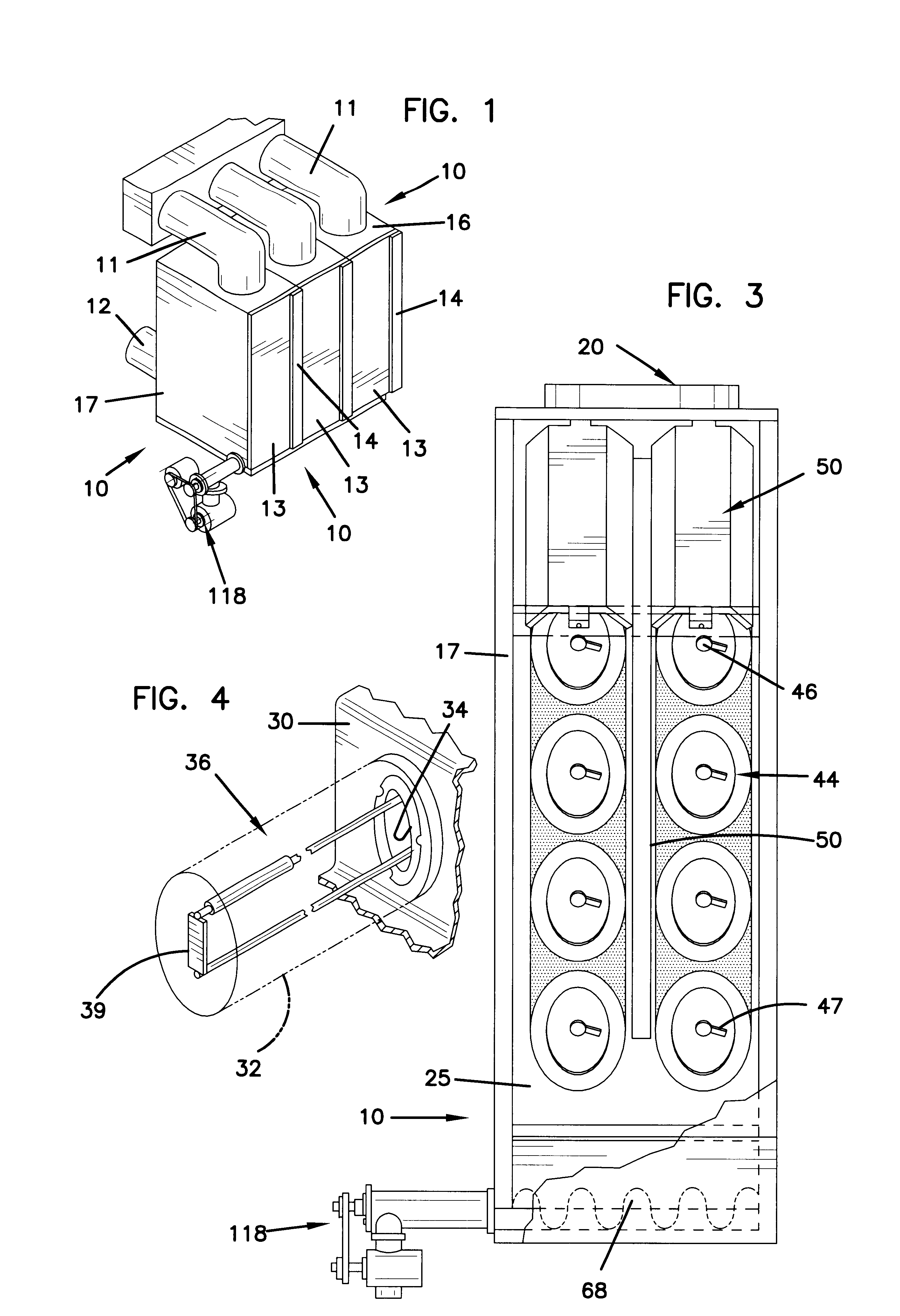
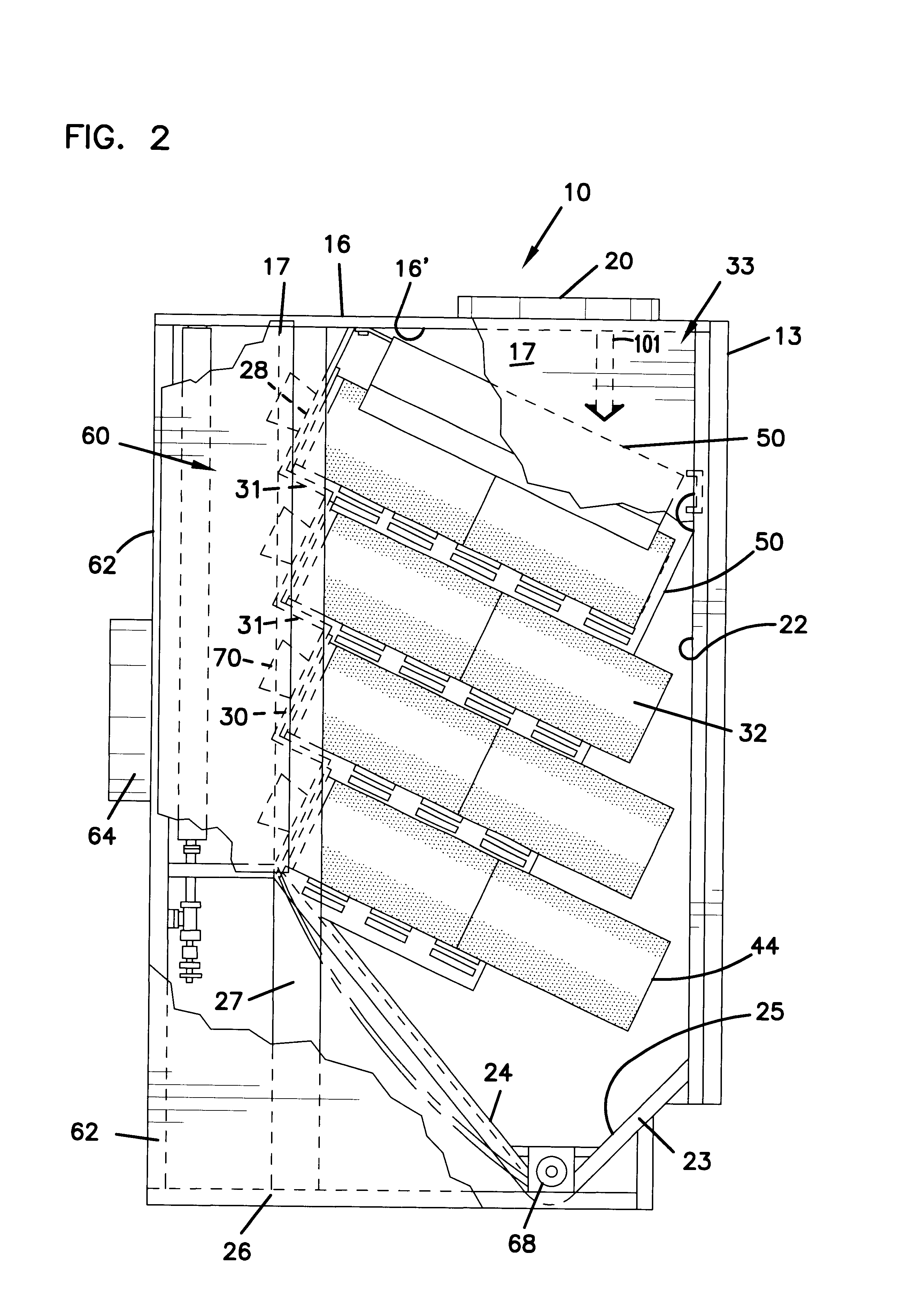
The enhanced performance of the non-cylindrical configuration according to the present disclosure is illustrated by comparisons made with a conventional cylindrical filter element 83 in an air filter assembly, such as illustrated in FIG. 9. The cylindrical filter element shown at 83 may be one constructed in accordance with that described in U.S. Pat. No. 4,171,963 (Schuler).

Computer modeling was done by using Computational Fluid Dynamics (CFD) software commercially available from Fluent, Inc. (of Lebanon, N.H.), which is a program commonly used for analyzing laminar and turbulent fluid flow problems. A Hewlett-Packard V-Class computer with 16 microprocessors was used to run the modeling.

CFD predicts flow through a volume (i.e., a domain) by using two equations: the continuity equation, .rho..sub.1 A.sub.1 v.sub.1 =.rho..sub.2 A.sub.2 v.sub.2 =constant, where .rho. is the fluid density, A is the cross-sectional area, and v is the fluid velocity; and the momentum conservation equatio...


PUM

PropertyMeasurementUnit
distanceaaaaaaaaaa
volumeaaaaaaaaaa
concentrationaaaaaaaaaa

Abstract

An air filter assembly for removing particulate matter from an incoming dirty air stream. The assembly includes a housing having an inlet, an outlet, a dirty air chamber and a clean air chamber and a non-cylindrical shaped elongated filter element arranged within the dirty air chamber constructed to remove particulate matter from an incoming air stream. A plurality of non-cylindrical filter elements are preferred. The non-cylindrical filter elements provide a decreased incoming air stream velocity when compared to conventional cylindrical filter elements having the same surface area. Alternately, the non-cylindrical filter elements allow an increase in the volume of incoming air when compared to conventional cylindrical filter elements having the same surface area.

Description

FIELD OF THE DISCLOSUREThe present disclosure is related to air filtering systems having non-cylindrical filter elements, and methods of using systems equipped with non-cylindrical filter elements.BACKGROUND OF THE DISCLOSUREMany industries often encounter particulate matter suspended in the atmosphere. In some industries, this particulate matter is a valuable product, for example, starch; it would be beneficial if these suspended particulate could be recovered and reintroduced into the process. For other industries, such as metal or wood working, the particulate matter may be simply dust; it is desirable to remove dust particles from the air in order to provide a clear working environment.Systems for cleaning an air or other gas stream laden with particulate matter include air filter assemblies that have filter elements disposed in a housing. The filter element may be a bag or sock of a suitable fabric or pleated paper. The gas stream, contaminated with particulate, typically is pa...

Claims


Application Information

Patent Timeline
Patent Type & Authority Patents(United States)
IPC IPC(8): B01D46/24B01D46/00
CPCB01D46/0013B01D46/002B01D46/2411B01D46/008B01D2267/30B01D46/58B01D46/88
Inventor KOSMIDER, KRISTOFER G.JOHNSON, STEVEN A.RAETHER, THOMAS D.
Owner DONALDSON CO INC
Why Eureka
Try Eureka