
Starting and welding device for DC TIG welder and method of operating same

a welding device and tig welding technology, applied in welding apparatus, arc welding apparatus, manufacturing tools, etc., can solve the problems of not being able to establish an arc for low current tig welding and then sustain the arc without scr, and achieve the effect of high capacity, reliably starting and sustained

Inactive Publication Date: 2002-05-14
LINCOLN GLOBAL INC
View PDF10 Cites 22 Cited by
  • Summary
  • Abstract
  • Description
  • Claims
  • Application Information

AI Technical Summary

Benefits of technology

The primary object of the present invention is the provision of a DC TIG welder with an SCR based DC power source for providing high current, wherein the welder can be operated at a low current without use of SCR spikes. The welder has an arc starting system which is positive in operation and novel in concept.
Another object of the present invention is the provision of a high capacity, SCR based DC TIG welder operable below about 5 amperes, which welder does not cause popping or melting of the tungsten electrode.
A further object of the present invention is the provision of an SCR based, DC TIG welder having a starting device so the welder can be operated at low currents without the need for current from an SCR rectifier stage and can be reliably started and sustained.

Problems solved by technology

Although starting procedures known in the prior art are successful for high welding currents in an SCR based DC TIG welder, such starting procedures are not capable of establishing an arc for low current TIG welding and then sustaining the arc without use of SCR current spikes.

Method used


Image

  • Starting and welding device for DC TIG welder and method of operating same
  • Starting and welding device for DC TIG welder and method of operating same
  • Starting and welding device for DC TIG welder and method of operating same

Examples


Embodiment Construction

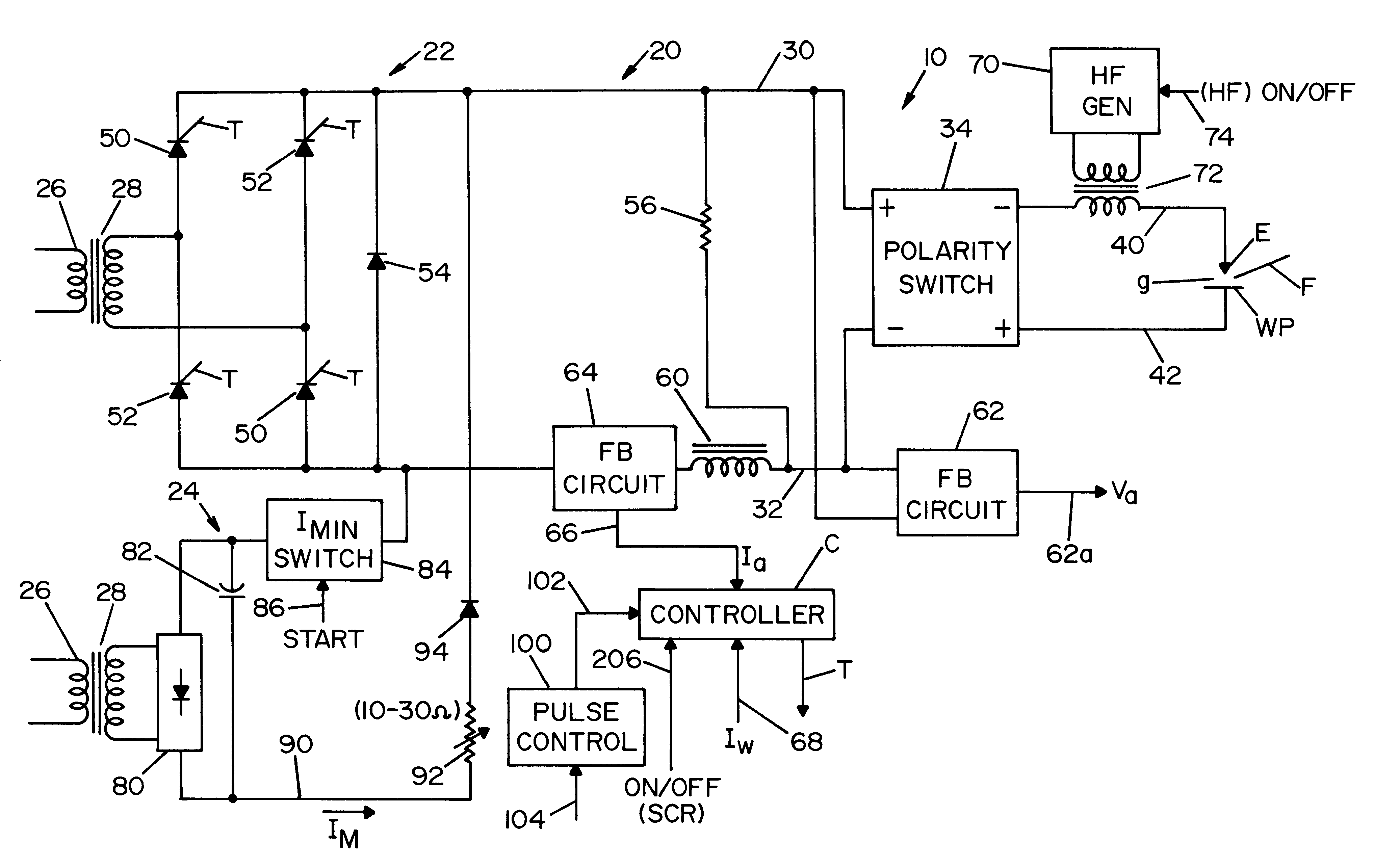
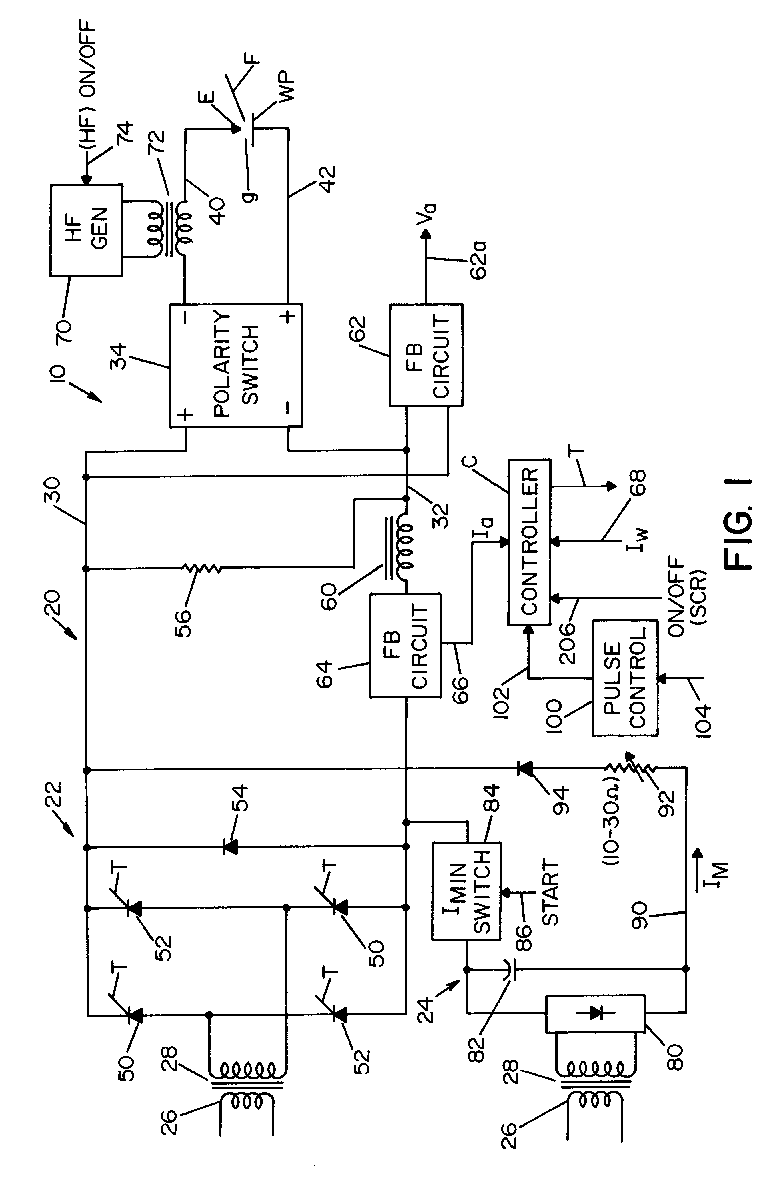
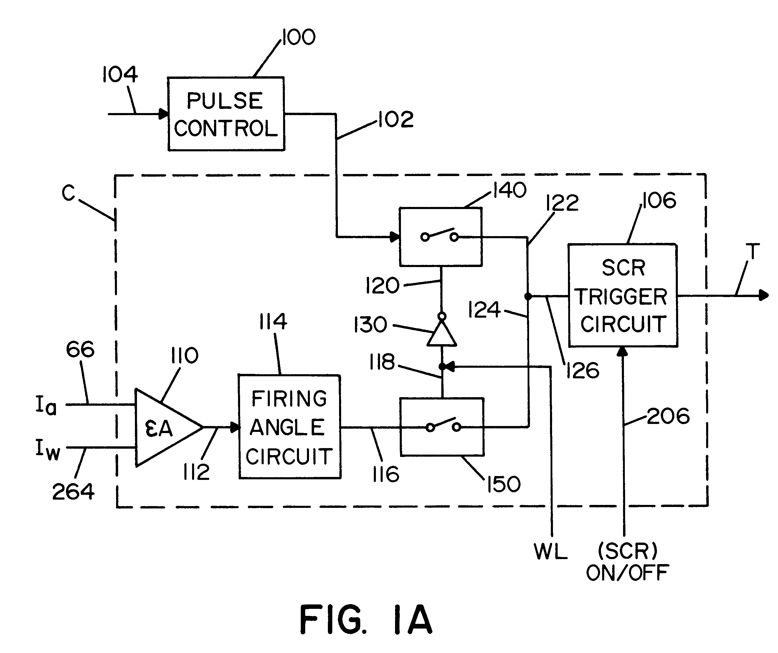
Referring now to the drawings, wherein the showings are for the purpose of illustrating the preferred embodiment of the invention only and not for the purpose of limiting same, FIG. 1 shows DC TIG welder 10 constructed in accordance with the preferred embodiment of the present invention. The welder is standard and operates at high welding currents. Welder 10 passes current across gap g between tungsten electrode E and workpiece WP. After an arc has been established in gap g, filler wire F (if used) is moved into the arc where it is melted and deposited on the workpiece for performing the welding operation. In accordance with the invention, power supply 20 has two stages driven by rectifiers. Stage 22 is an adjustable stage for high current welding. Stage 24 is a fixed stage with a settable low current output for low current welding. Both of these stages are driven by single phase input 26 through a step-down transformer 28 to create current in output leads 30, 32. These leads define...


PUM

PropertyMeasurementUnit
Timeaaaaaaaaaa
Currentaaaaaaaaaa
Currentaaaaaaaaaa

Abstract

A DC TIG welder operable at a set low current level under about 5 amperes in a welding circuit including an electrode separated from a workpiece by a gap, the welder having an output welding current adjustable above the low current and driven by a constant current power supply with a first rectifier having an output current controlled by the firing phase of SCRs in an SCR network, a second rectifier settable at the low current and a sensor for sensing arc voltage. The welder further comprises: a circuit to deactivate the SCRs when the output welding current is equal to or less than the set low current and an arc starting device to cause the first rectifier to output a high pulse by operation of the SCRs of the network.

Description

The present invention relates to the art of electric arc welding and particularly a starting device for use in a DC TIG welder operated by an SCR input and capable of sustaining a welding arc at a low current.INCORPORATION BY REFERENCEIn TIG welding a tungsten electrode is spaced from a workpiece to define a gap across which an arc is created for melting a filler wire moved into the arc. This type of welding presents problems relating to the starting of the arc at the start of the TIG welding process. Several procedures are known to start the arc when the TIG welder is operated at over about 5 amperes. Starting procedures and background technology regarding arc starting is discussed in De Coster U.S. Pat. No. 6,075,224. This patent illustrates an arc starter circuit using high frequency. As background information, this patent is incorporated by reference. The present invention relates to a high current DC TIG welder which is operable at a low weld current, such as a current in the g...

Claims


Application Information

Patent Timeline
IPC IPC(8): B23K9/06B23K9/067
CPCB23K9/0673
Inventor SAMODELL, RALPH M.NGUYEN, TRANG D.
Owner LINCOLN GLOBAL INC
Learn More