Conductive polymer current-limiting fuse

a current-limiting fuse and polymer technology, applied in current-responsive resistors, over-voltage protection resistors, varistors, etc., can solve the problems of increasing the potential for serious damage, brittleness and hardness of materials, and not being easily deformed

Inactive Publication Date: 2002-05-14
EATON CORP
View PDF14 Cites 25 Cited by
  • Summary
  • Abstract
  • Description
  • Claims
  • Application Information

AI Technical Summary

Benefits of technology

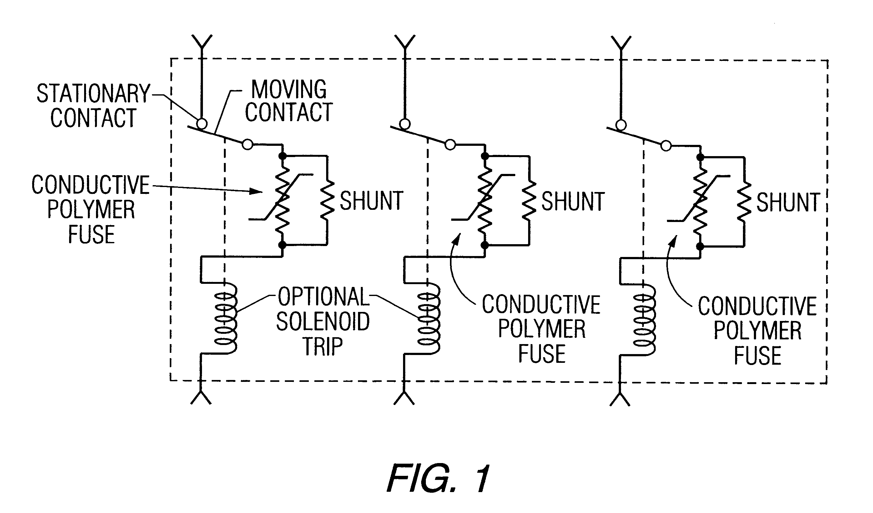
The invention provides a high power fuse capable of increasing the current limiting capacity of mechanical circuit breakers when connected in electrical series therewith, by inserting a series resistance upon the occurrence of a fault current at which the mechanical circuit breaker will throw.
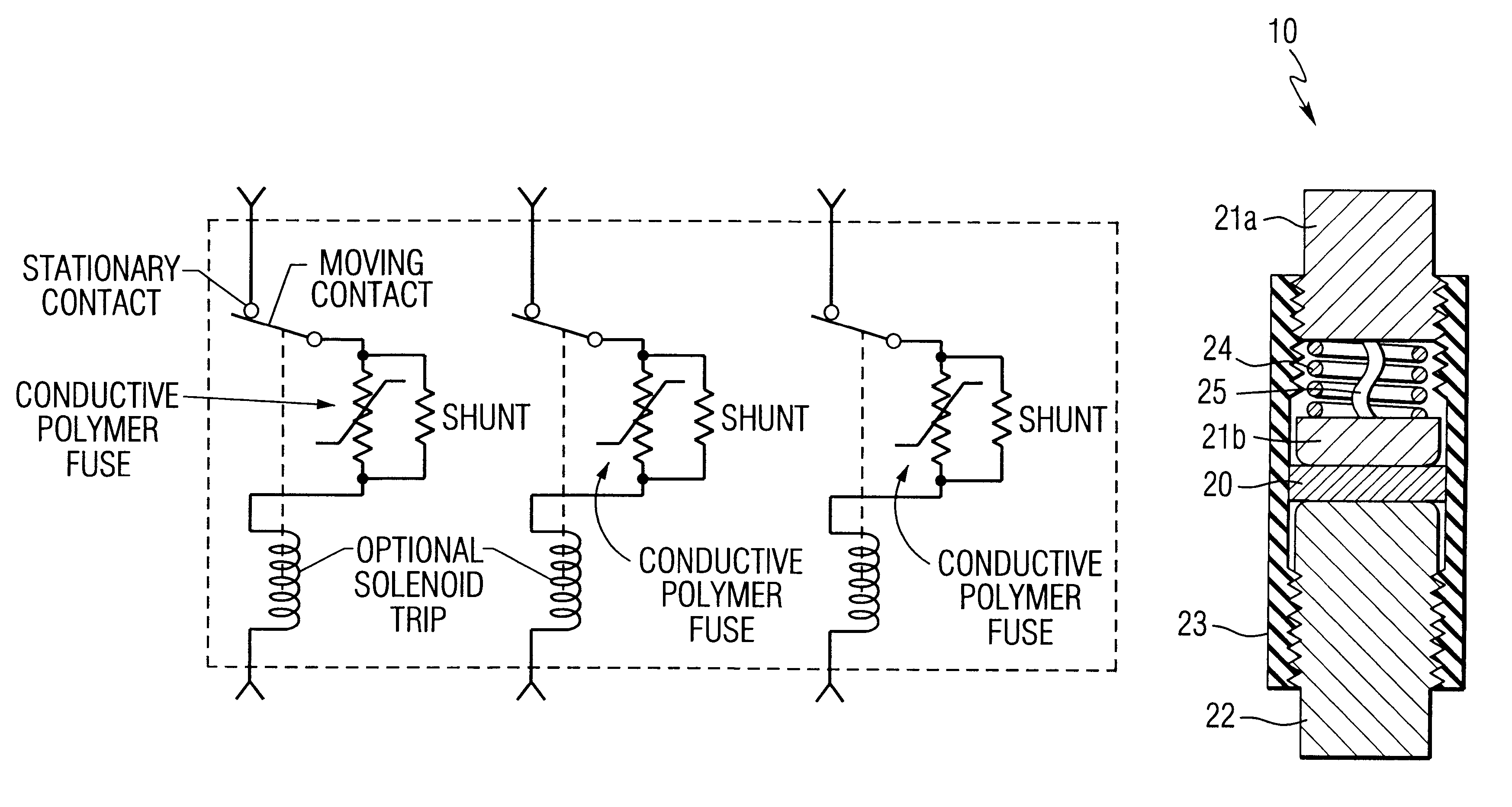
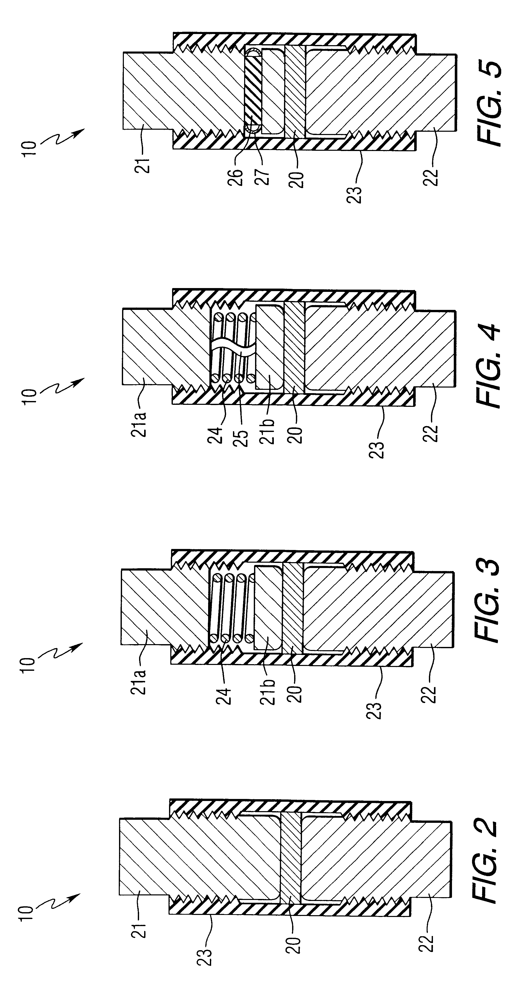
According to an aspect of the invention, a fuse is provided with a metal filled elastomer, two electrodes, a spring, enclosure, and a commutation shunt device. The metal filled elastomer is held in contact with a pair of electrodes through the application of a force sufficient to deform the elastomer at the interface with the electrodes, resulting in a low device resistance.

Problems solved by technology

If the fault current is not quickly cut off, the potential for serious damage is increased.
However, an electrically conductive filler impairs the mechanical properties of the plastic.
The material becomes brittle and hard and is therewith not readily deformed.
These materials are therefore less useful as pressure transducers with pressure contacts.
A further limitation of carbon-filled plastics resides in their relatively high resistivity, typically one 1 Ohm cm and higher, which limits applications to low power.
On the other hand, metal-filled plastics can be produced with significantly lower resistivity, lower than 0.5 Ohm cm, although voltage or tension stability becomes very poor, and consequently these materials are not suited as overload protectors.
However, the break-time of conventional circuit breakers is several milliseconds, with even the fastest circuit breakers taking 3 to 5 ms to open and interrupt fault currents.
Due to various mechanical constraints and the continuation of conduction as an are is struck and extinguished between the separating contacts, traditional circuit-breaker technology leaves little potential for further reductions in break-times.
The metal filled elastomer is held in contact with a pair of electrodes through the application of a force sufficient to deform the elastomer at the interface with the electrodes, resulting in a low device resistance.
Excessively high force can result in electrical breakdown and failure of the fuse during transition.
The hardness of the conductive polymer and the type of polymer may limit this design.

Method used


Image

  • Conductive polymer current-limiting fuse
  • Conductive polymer current-limiting fuse
  • Conductive polymer current-limiting fuse

Examples


Embodiment Construction

prototype laboratory device was made in the following manner. An uncured metal fillet RTV silicone elastomer was used to make a flat one inch diameter 0.065 inch thick disk of conductive elastomer. A section measuring 0.5 inch.times.0.75 inch.times.0.065 inch was cut from the disk and placed against a flat copper electrode (0.375 inch wide.times.1 inch long.times.0.020 inch thick) in a fixture with a threadably adjustable screw for setting the pressure on the elastomer. The other electrode consisted of a 3 / 8 inch diameter 0.5 inch long copper slug with a blunt nose radius on the end contacting the elastomer. A polyethylene rod, 0.25 inch diameter.times.0.5 inch long, was placed between the copper slug and a bolt used to apply pressure to the elastomer. The bolt was adjusted to provide the desired electrical resistance (approximately 3 mOhm) between the copper slug and the flat electrode. Electrical connections were made between the flat copper electrode and a second piece of 0.020 i...


PUM


Abstract

Conductive polymer current-limiting fuses. when connected in series with conventional mechanical circuit breakers, exhibit extremely low let-through values. Particularly, conductive polymer current-limiting fuses based on conductive elastomeric material are disclosed which exhibit extremely low let-through values, namely less than 5,000 A2s with a switch current of 1.79 kAp, preferably less than 2,500 A2s, most preferably no more than 2,250 A2s.

Description

This invention relates to current-limiting fuses containing a conductive polymer exhibiting a sharp increase in electrical resistance at a threshold current. The polymer is coupled in series with mechanical breaker contacts and is resistively heated to the threshold temperature in the event of a fault current, to limit current as the breaker opens. A commutation shunt resistance can be coupled in parallel with the polymer. The invention relates to conductive polymer current-limiting fuses which exhibit extremely low let-through values. More particularly, the conductive polymer current-limiting fuses are based on metal-filled elastomer material and exhibit let-through values less than 5,000 A.sup.2 s with a switch current of 1.79 kA.sub.p, preferably less than 2,500 A.sup.2 s, most preferably no more than 2,250 A.sup.2 s. Several embodiments are disclosed, including an arrangement is which at least one electrode is in free surface contact with a planar polymer element and urged again...

Claims


Application Information

Patent Timeline
Patent Type & Authority Patents(United States)
IPC IPC(8): H01C7/12
CPCH01C7/126
Inventor SHEA, JOHN J.HANNA, WILLIAM K.
Owner EATON CORP
Why Eureka
Try Eureka