Pump assembly for a slip-controlled hydraulic brake system for a vehicle

Inactive Publication Date: 2002-05-21
ROBERT BOSCH GMBH
View PDF6 Cites 29 Cited by
  • Summary
  • Abstract
  • Description
  • Claims
  • Application Information

AI Technical Summary

Benefits of technology

In the pump assembly according to the invention the drain discharges into the cylinder bore, between the seal toward the eccentric element and the eccentric element chamber. Leaking fluid from the piston pump that has overcome the seal toward the eccentric element flows through the drain out of the cylinder bore before reaching the eccentric element chamber. This prevents leaking fluid from the piston pump from reaching the interior of the eccentric element chamber. As a result, mixing of leaking fluid (brake fluid) with lubricant or bearing oil of an eccentric element bearing or motor bearing, which is highly undesirable, does not occur. Since no leaking fluid from the piston pump reaches as far as the eccentric element chamber, leakage fluid is prevented from reaching an eccentric element bearing or motor bearing or the pump motor. Damage to an eccentric element bearing or motor bearing or the pump motor from brake fluid is thus precluded. Oil from an eccentric element bearing or motor bearing is prevented from reaching the drain and being able to stop up a sintered body that might be present. The drainage of leakage fluid is thus assured permanently.
The pump assembly of the invention is intended in particular as a pump in a brake system of a vehicle and is used to control the pressure in wheel brake cylinders. Depending on the type of brake system, the abbreviations ABS (for anti-lock brake system), TCS (traction control system), ESP (electronic stability program) and EHB (electrohydraulic brake system) are used for such brake systems. In the brake sys

Problems solved by technology

The known pump assembly has the disadvantage that the pump assembly additionally requires the check valve, and that the check valve must be inserted into the drain during the assembly of the pump assembly, which means additional assembly effort and expense.
Invading dirt can moreover impair the closing function of the check valve.
This pump assembly has the disadvantage that oil can get into the drain from an eccentri

Method used


Image

  • Pump assembly for a slip-controlled hydraulic brake system for a vehicle
  • Pump assembly for a slip-controlled hydraulic brake system for a vehicle

Examples


Embodiment Construction

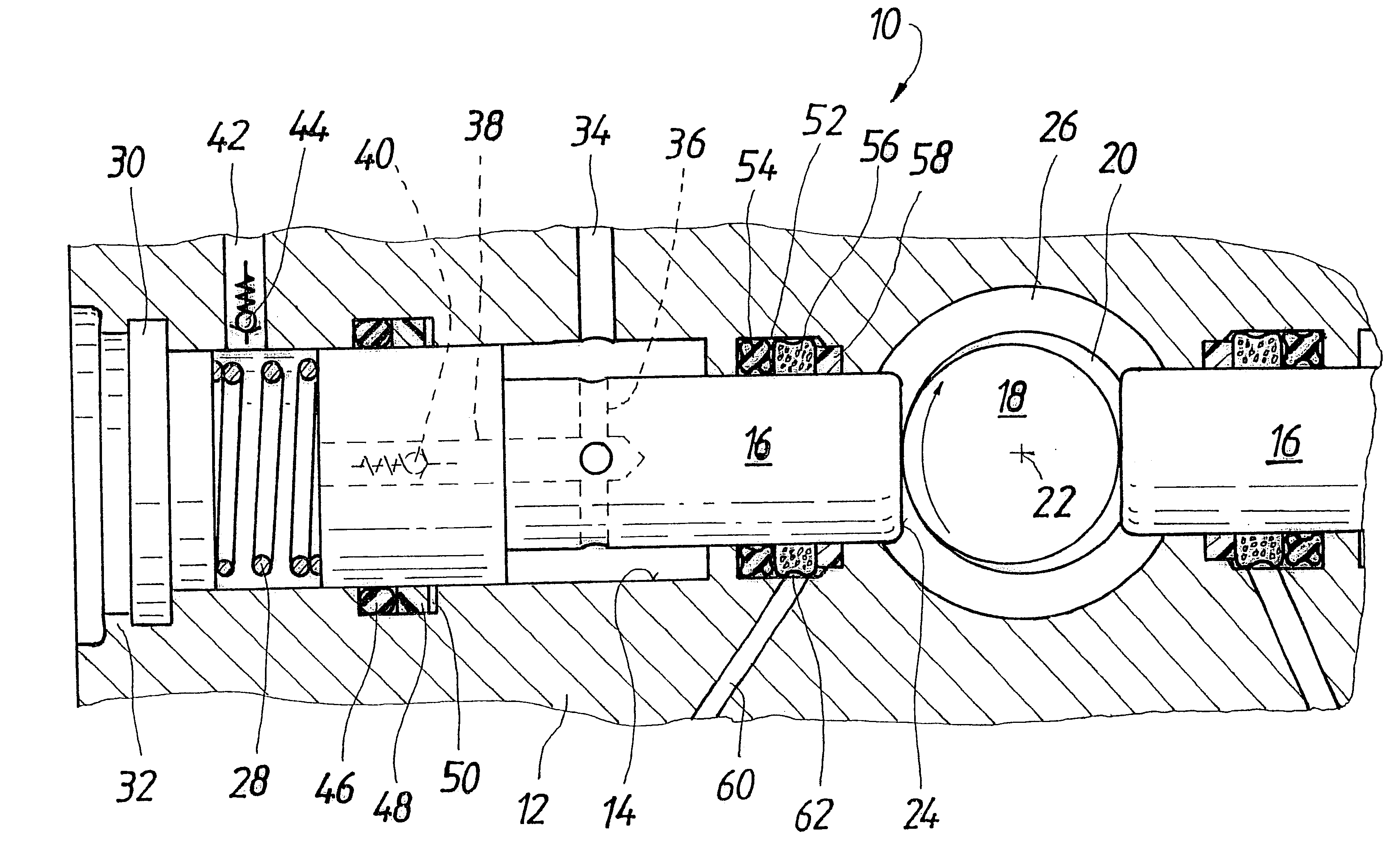
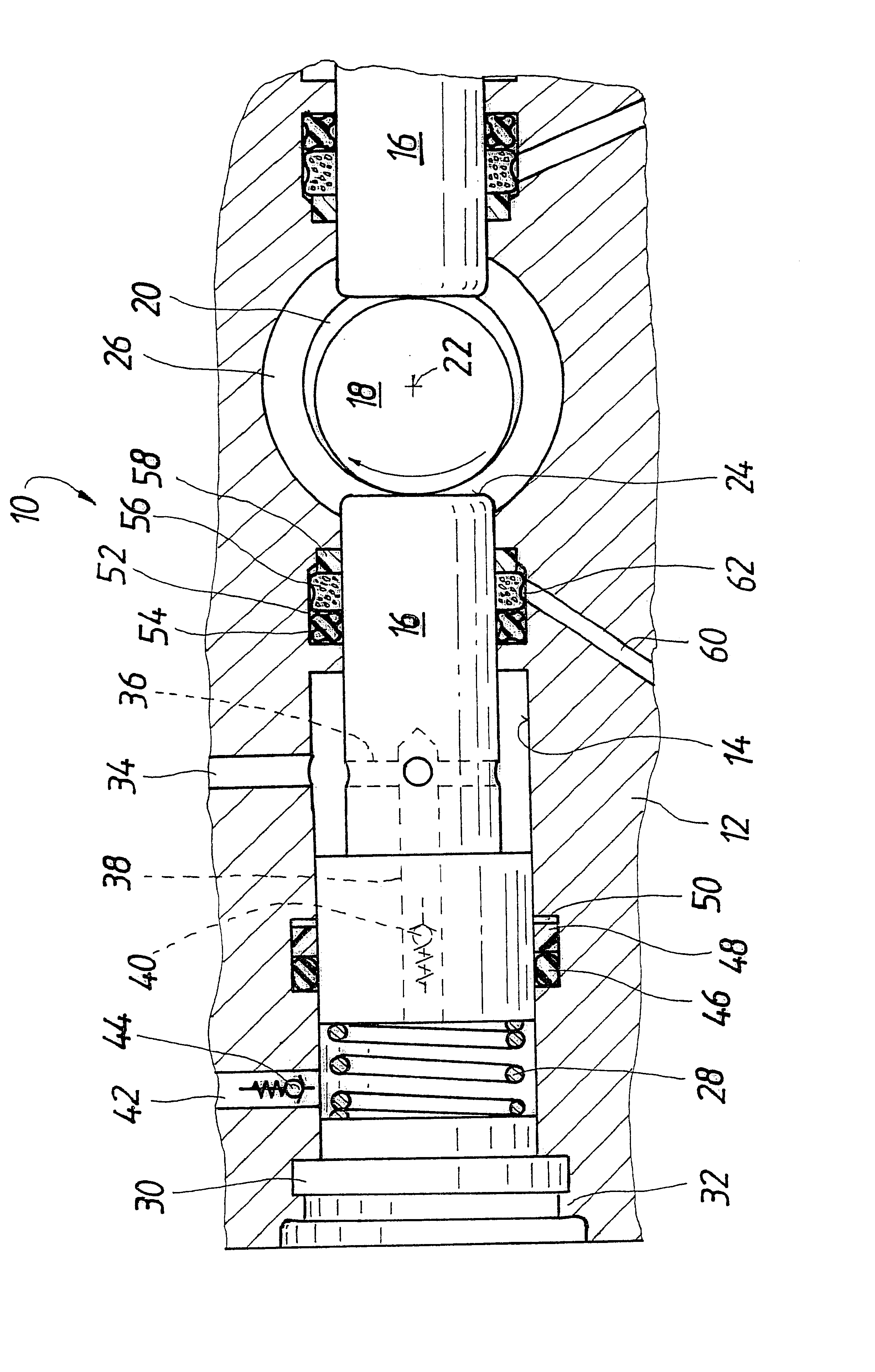
The pump assembly according to the invention, identified overall by reference numeral 10, is inserted into a hydraulic block 12 of a slip-controlled hydraulic brake system for a vehicle, not otherwise shown. In the hydraulic block 12, of which for the sake of simplicity the drawing shows only a fraction surrounding the pump assembly 10, there are further hydraulic components, such as magnet valves, hydraulic reservoirs, and damper chambers, which are connected hydraulically to one another and to the pump assembly 10. In a manner known per se, the hydraulic block 12 is connected via a brake line to a brake cylinder, not shown, that is actuatable with a foot-actuated brake pedal or a manual brake lever, and wheel brake cylinders, not shown, are connected to the hydraulic block 12 via brake lines. The hydraulic block 12 forms a pump housing of the pump assembly 10 according to the invention and will hereinafter be called the pump housing.

A continuous cylinder bore 14 is provided in the...


PUM


Abstract

A pump assembly having a piston pump, which is driven by an eccentric element. To prevent leakage brake fluid from reaching an eccentric element chamber, a groove surrounds the pump piston in the pump housing and a seal and a porous metal sintered ring is inserted into the groove. A drain which extends obliquely downwardly from the groove drains leakage fluid from the sintered ring.

Description

PRIOR ARTThe invention relates to a pump assembly for a slip-controlled hydraulic brake system for a vehicle.One such pump assembly is known from German Patent Disclosure DE 42 39 361 A1. As its pump motor, the known pump assembly has an electric motor, on whose motor shaft an eccentric element is mounted in a manner fixed against relative rotation. A pump piston of a piston pump of the pump assembly rests with an end face on a circumference of the eccentric element. The pump piston is received axially displaceably in a cylinder bore of a pump housing. The pump piston can be guided axially displaceably in the pump housing directly, or in a bush inserted into the pump housing. When the eccentric element is driven to rotate by the pump motor, the pump piston resting on the circumference of the eccentric element is driven to execute an axially reciprocating stroke motion in the cylinder bore, which in a manner known per se for piston pumps brings about pumping of brake fluid. As the ec...

Claims


Application Information

Patent Timeline
IPC IPC(8): B60T8/40B60T17/00B60T17/02F04B1/04F04B1/00F04B1/02F04B9/04F04B53/14
CPCB60T8/4031F04B1/0443B60T17/02
Inventor SCHAEFER, ERNST-DIETER
Owner ROBERT BOSCH GMBH
Why Eureka
Try Eureka