Contactless or hybrid contact-contactless smart card designed to limit the risks of fraud

a smart card and contactless technology, applied in the field of contactless smart cards, can solve the problems of module-antenna or chip-antenna connection breaking, mediocre mechanical properties of monobloc cards in terms of restitution of absorbent stresses, and weak bonding joints

Inactive Publication Date: 2002-05-21
ASK SA (FR)
View PDF26 Cites 153 Cited by
  • Summary
  • Abstract
  • Description
  • Claims
  • Application Information

AI Technical Summary

Problems solved by technology

However, a card of this type has several major drawbacks.
The most significant drawback is that the plastic heat bonding operation, implemented during the lamination process, leads to a monobloc card having mediocre mechanical properties in terms of the restitution of absorbed stresses.
The mechanical strength of the bonding joints is subjected to great strain which can cause the module-antenna or chip-antenna connection to break.
Besides large-scale organized fraud which requires significant means and highly-skilled technical specialists and which consists in reproducing the behavior of a real card by using another technical component, individual fraud is the most insidious in that it involves individuals who are the customers of the card issuing organization.
One can find occasional fraud, which consists in using the card for a purpose other than the one it was designed for, or in not respecting the usage conditions prescribed by the card's issuer.
Indirect intentional fraud also exists in which a user, unfamiliar with the technique, tries to obtain a service for which a card is not programmed.
It is thus relatively easy for this type of individual to destroy the card as cleanly as possible, by intense repetitive bending, when in possession of a card sold with a credit (telephone cards, mass transit cards, highway toll stations), and that this credit is exhausted or almost exhausted without it being possible to prove the inte

Method used


Image

  • Contactless or hybrid contact-contactless smart card designed to limit the risks of fraud
  • Contactless or hybrid contact-contactless smart card designed to limit the risks of fraud
  • Contactless or hybrid contact-contactless smart card designed to limit the risks of fraud

Examples


Embodiment Construction

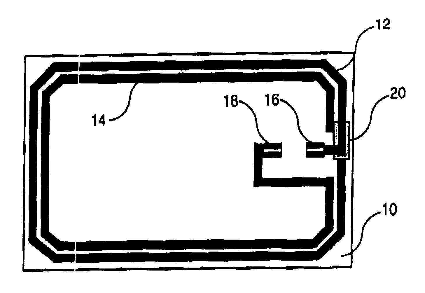
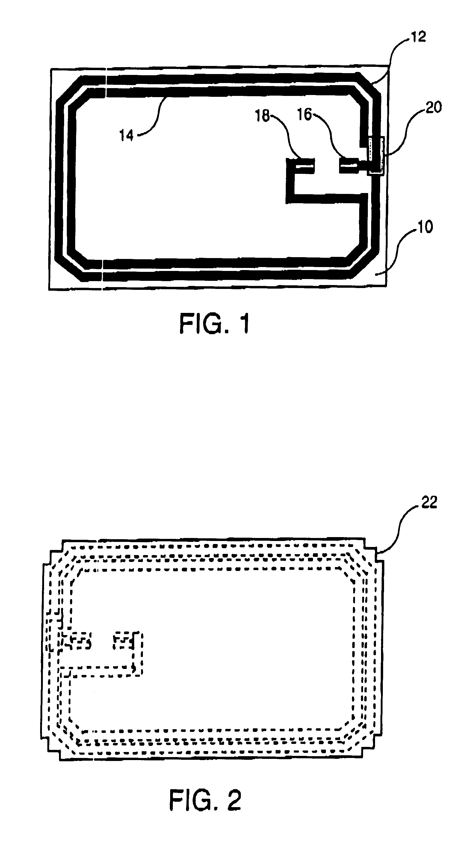
In FIG. 1, the smart card according to the invention consists of a paper support 10 on which an antenna is screen printed. The antenna consists of two turns 12 and 14, screen printed with an electrically conductive polymer ink, loaded with conductive elements such as silver, copper or carbon. One end of each turn is connected to one of the antenna contacts to the module which are also screen printed, turn 12 being connected to contact 16 and turn 14 to contact 18. The turns are interconnected by an electric bridge, most commonly referred to as the "cross-over" (not shown in the figure). An insulating strip of dielectric ink 20 is screen printed between the cross-over and turn 12. The antenna drawing is reversed in relation to the normal drawing of an antenna for an ISO format smart card. This special configuration provides a hybrid contact-contactless smart card with a cavity for housing the module, milled into the card body which is opposite the side of the support bearing the scre...


PUM


Abstract

The invention relates to a contactless or hybrid contact-contactless smart card, including an antenna on a support, this antenna being formed by at least one turn of electrically conductive ink which is screen printed on the support, two card bodies 24 on each side of the support, each of the card bodies consisting of at least one layer of plastic material, and a chip or module 26 connected to the antenna. The support is made of paper and features cutouts 22 in each corner at which the two card bodies are welded together, thus giving its capacity to delaminate, when the card is bent, at the location where the forces were generated, which highlights any act of deliberate damage a posteriori as the card retains the traces of the bending, and represents a countermeasure against fraud.

Description

The present invention relates to smart cards, and more specifically a contactless or hybrid-contact contactless smart card for which the antenna is on a support made of fibrous material such as paper.PRIOR ARTThe contactless smart card is a system being used increasingly in various sectors. In the transport sector, the card has been developed as a means of payment. The same holds true for the electronic wallet. Many companies have also developed identification means for their personnel using contactless smart cards.The exchange of information between a contactless card and the reader takes place via remote electromagnetic coupling between an antenna embedded in the contactless card and a second antenna in the reader. In order to create, store and process the information, the card is equipped with a chip or an electronic module which is connected to the antenna. The antenna and the chip are generally located on a dielectric support made of plastic material (polyvinyl chloride (PVC), ...

Claims


Application Information

Patent Timeline
IPC IPC(8): G06K19/073G06K19/02G06K19/077B42D15/10G06K19/10
CPCG06K19/02G06K19/073G06K19/07372G06K19/07749G06K19/07769G06K19/07779G06K19/07783H01L2224/16G06K19/07
Inventor KAYANAKIS, GEORGES
Owner ASK SA (FR)
Why Eureka
Try Eureka