PLL circuit for digital display apparatus

a digital display and circuit technology, applied in the field of pll circuits for digital display apparatuses, can solve the problems of disturbing images, significant phase difference, blackening the screen, even temporarily,

Inactive Publication Date: 2002-05-21
FUJITSU GENERAL LTD
View PDF22 Cites 17 Cited by
  • Summary
  • Abstract
  • Description
  • Claims
  • Application Information

AI Technical Summary

Benefits of technology

It is therefore an object of the present invention to provide a PLL circuit which can output an optimal internal sync signal even when lock-off of a PLL circuit in a digital display apparatus occurs.

Problems solved by technology

However, blackening the screen, even temporarily, is not a preferable solution.
Further, the skew itself causes a significant phase difference.
During that period, the system clock that should be output becomes asynchronous with the external horizontal sync signal, disturbing images.
Although a PLL circuit is originally so designed as to follow up a slight variation in the external horizontal sync signal, the aforementioned occurrence of a large phase variation is not anticipated.
With respect to the occurrence of a skew pulse or an added pulse, therefore, it takes a long time to implement lock-in from the unlocked state.

Method used


Image

  • PLL circuit for digital display apparatus
  • PLL circuit for digital display apparatus
  • PLL circuit for digital display apparatus

Examples


first embodiment

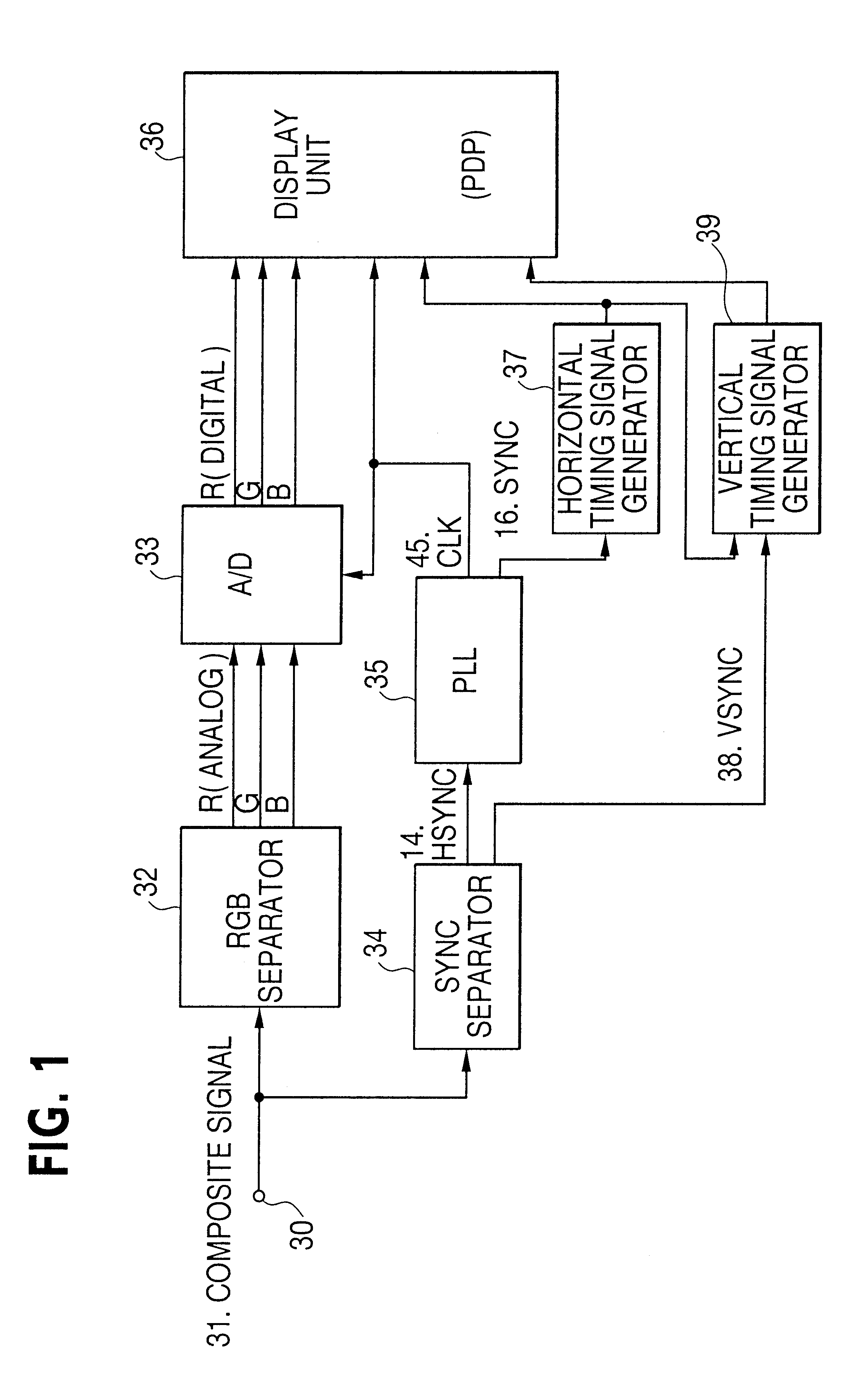
According to this invention, as the internal sync signal (SYNC) 16, the comparison signal is used when the PLL circuit is in a locked state, and the external horizontal sync signal (EHD) 14 externally supplied is used in an unlocked state, as mentioned above. Detection of lock-off is carried out by monitoring a phase difference between the external horizontal sync signal 14 and the comparison signal.

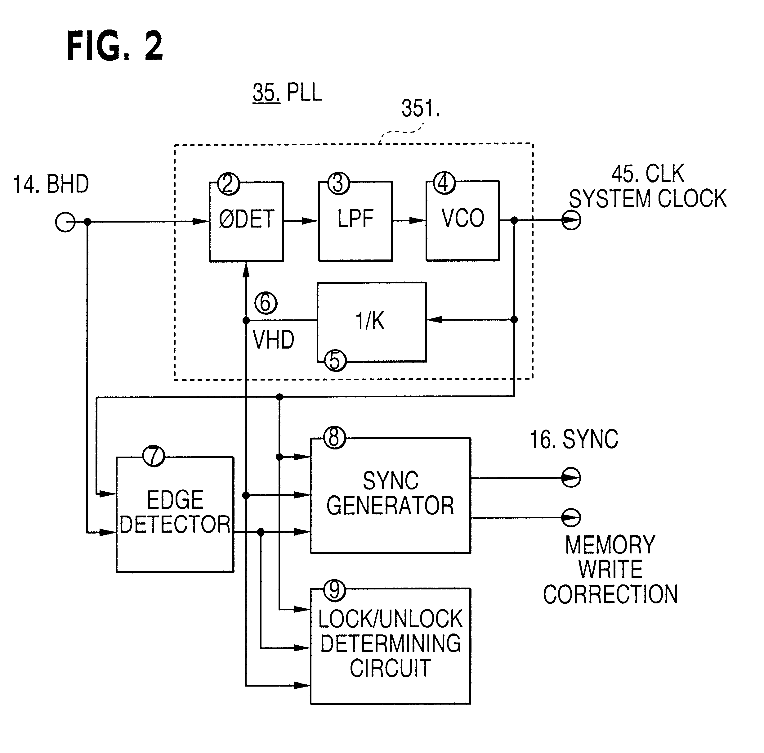
FIG. 2 is a block diagram of the internal structure of the PLL circuit 35 in FIG. 1. FIG. 3 is a timing chart for explaining how the PLL circuit 35 switches the internal sync signal (SYNC) 16.

Input to the PLL circuit 35 in FIG. 2 is the horizontal sync signal (EHD) 14, which is separated from the composite image signal by the sync separator 34 as mentioned above. As outputs, the system clock signal (CLK) 45 and the internal sync signal (SYNC) 16 are output. "2" denotes a phase comparator which compares the phase of the horizontal sync signal EHD 14, input externally, with the phase of a ...

second embodiment

A second embodiment of this invention will now be described. In this invention, even when the external horizontal sync signal (Hsync) 14 includes a skew pulse or an extra pulse or has a pulse drop-out or the like, the lock-in state of the PLL circuit 35 can be maintained as much as possible, preventing the circuit from going into an unstable unlocked state for a long period of time. As a result, the PLL circuit 35 can generate a stable system clock signal.

FIG. 6 is a block diagram exemplifying a PLL circuit according to the second embodiment of this invention. FIG. 6 shows the PLL circuit 35 in FIG. 1 excluding the sync separator 34 in FIG. 1 and an equivalent pulse killer circuit 341 which accompanies the separator. The equivalent pulse killer circuit 341 removes an equivalent pulse to bisect a horizontal sync signal, which is constituted by a double frequency in order to cope with the interlace type CRT in a case of the normal NTSC composite image signal.

A portion 351 surrounded b...

third embodiment

this invention provides a synthesizing circuit which has both the function of the PLL circuit of the first embodiment and the function of the PLL circuit of the second embodiment. FIG. 13 is a block diagram of the internal structure of such a synthesizing circuit. Referring to FIG. 13, "351" denotes an ordinary PLL circuit portion, "352" denotes the PLL circuit according to the second embodiment and "35" denotes a PLL circuit to which the function of the PLL circuit of the first embodiment is added.

In the synthesizing circuit according to the third embodiment, the PLL circuit of the first embodiment serves to detect a phase difference between the external horizontal sync signal 14 and the comparison signal 6, and when there is a phase difference, it determines the state as an unlocked state and switches the internal sync signal 16 to the external sync signal 14. The internal sync signal 16 during the unlock-in period is kept to the external sync signal 14.

Further, the PLL circuit of...


PUM


Abstract

A PLL circuit is provided with a lock/unlock detection circuit which detects the locked or unlocked state of the PLL circuit by comparing the phases of a horizontal synchronizing signal with each other and an internal synchronizing signal generating circuit which outputs the comparison signal as an internal synchronizing signal when the locked state is detected or outputs the horizontal synchronizing signal as an internal synchronizing signal when the unlocked state is detected. Another mode of a PLL circuit is provided with a skew detecting circuit which resets a frequency dividing circuit upon detecting a skew which is deviated from a normal period in an external synchronizing signal, generates a dummy pulse upon detecting that no skew occurs in the external synchronizing signal in the normal period, and generates a reference signal in combination of the dummy pulse with the external synchronizing signal. When the skew detection circuit detects a skew, the circuit also resets a phase comparator circuit. A digital display apparatus having such a PLL circuit prevents disturbance of the image when the PLL circuit is in an unlocked state or a skew occurs.

Description

The present invention relates to a PLL (Phase Locked Loop) circuit for a digital display apparatus, and, more particularly, to a PLL circuit which can avoid, as much as possible, disturbance of an image at the time the PLL circuit is unlocked and locked in.For digital display apparatuses, such as a PDP (Plasma Display Panel) apparatus and an LCD (Liquid Crystal Display) apparatus, which internally carry out digital processing in accordance with a horizontal sync signal and a vertical sync signal, both supplied in an analog form, and an image signal having a predetermined timing based on those sync signals, an internal system clock signal which is synchronous with the horizontal sync signal or the like is generated by using a PLL circuit.An input analog image signal is sampled and converted to a digital signal by using a system clock signal whose frequency is K times the frequency of the horizontal sync signal generated by a PLL circuit and an internal sync signal or a comparison sig...

Claims


Application Information

Patent Timeline
Patent Type & Authority Patents(United States)
IPC IPC(8): G09G3/20H03L7/08H04N5/12H03L7/095H03L7/16H03L7/199H04N5/66G09G5/00
CPCG09G5/008H03L7/0807H03L7/199H04N5/126H03L7/095H04N5/66H04N5/12
Inventor NISHIMURA, EIZOKONDOU, SATORUKURITA, MASANORI
Owner FUJITSU GENERAL LTD
Why Eureka
Try Eureka