En route spacing system and method

a technology of en route spacing and aircraft, applied in direction finders using radio waves, instruments, reradiation, etc., can solve the problems of reducing the performance of conflict-probe decision support, concentrating traffic unnecessarily, and inefficient conformance actions directly affecting airspace users, so as to reduce workload and fuel consumption, avoid conflicts, and reduce the number of corrective clearances

Inactive Publication Date: 2002-05-21
NAT AERONAUTICS & SPACE ADMINISTATION UNITED STATES OF AMERICA THE AS REPRESENTED BY THE SEC
View PDF5 Cites 109 Cited by
  • Summary
  • Abstract
  • Description
  • Claims
  • Application Information

AI Technical Summary

Benefits of technology

A primary advantage of the present invention is that it reduces workload and fuel consumption by reducing the number of corrective clearances (needed to achieve flow-rate conformance while avoiding conflicts) and the more efficient distribution of spacing workload upstream and across sectors.
is that it reduces workload and fuel consumption by reducing the number of corrective clearances (needed to achieve flow-rate conformance while avoiding conflicts) and the more efficient distribution of spacing workload upstream and across sectors.
Other objects, advantages and novel features, and further scope of applicability of the present invention will be set forth in part in the detailed description to follow, taken in conjunction with the accompanying drawings, and in part will become apparent to those skilled in the art upon examination of the following, or may be learned by practice of the invention. The objects and advantages of the invention may be realized and attained by means of the instrumentalities and combinations particularly pointed out in the appended claims.
The accompanying drawings, which are incorporated into and form a part of the specification, illustrate several embodiments of the present invention and, together with the description, serve to explain the principles of the invention. The drawings are only for the purpose of illustrating a preferred embodiment of the invention and are not to be construed as limiting the invention. In the drawings:
FIG. 2 illustrates Denver Center MIT restrictions from data in June 1996;

Problems solved by technology

Current-day practices for MIT-spacing increase controller workload, concentrate traffic unnecessarily, and degrade the performance of conflict-probe (CP) decision support.
Today's procedures also result in inefficient conformance actions that directly impact the airspace user.
There are many factors that impact air traffic operations, but primary factors include conflicts and Traffic Flow Management (TFM) flow-rate restrictions.
Although flow restrictions only impact a percentage of flights, the resulting deviations are significant compared to those required for maintaining basic radar separation.
Furthermore, the lack of ATC-sector decision support for flow-rate conformance planning and execution results in a significant degradation in the performance of conflict probe.
Conflict probe lacks the trajectory "intent" of the controller's plan for flow-rate conformance leading to the "conflict probing" of the "wrong" trajectories (thus increasing the probe's rate of false alarms and missed alerts).
This degradation occurs in just the sort of "problem" airspace where the air transport industry needs automation assistance such as conflict probe.
Even with arrival metering operations, many flights will still be subject to MIT-spacing restrictions.
Second, the limited number of arrival-metering sites (i.e., CTAS-TMA-adapted airports) leaves the remaining airports to depend on MIT-spacing procedures.
Third, there is a need to occasionally propagate delays upstream of terminal airspace prior to the arrival-metering horizon.
However, there has been little effort on near-term controller tools to assist with flow-rate conformance, let alone integration with conflict detection / resolution.
As terminal-area delays grow, Chicago Center must throttle the arrival flow.
Although today's "manual" MIT-spacing techniques are straightforward to implement, there are several disadvantages related to their path-dependent nature.
Without automation assistance, it would be difficult for sector controllers to visualize and space their flights relative to flights in other sectors that are orthogonal to the flow.
Depending on the natural distribution of flight paths, these re-route actions add a significant penalty.
Although speed control can help fine-tune spacing under current procedures, it is often too little to establish spacing because of performance mismatches and limited range within a sector (for speed changes to take effect).
In-trail flows also reduce the opportunity for faster aircraft to pass slower. ones when the faster aircraft would naturally arrive first at the spacing-reference fix.
Once spacing is established within a stream, additional deviations may result from conflicts with crossing traffic.
First is the workload required to establish the stream.
Second, controllers must rely on tactical techniques to establish spacing based on experience and trial and error.
Third, in-trail techniques force flights into streams that concentrate traffic density and workload in the "spacing" sectors as opposed to distributing flights across sectors.
Finally, the spacing sectors are impacted in terms of conflict detection and resolution because the tactical nature of current-day spacing techniques negatively impacts the operational use of CP tools.
This is due to several factors including the controller workload associated with flight plan amendments and the difficulty controllers would have in reflecting today's relatively tactical spacing techniques in a flight-plan amendment.
As a result, CP may experience a greater rate of false alarms (due to the lack of spacing-conformance intent) and missed alerts (if the controller's conformance actions result in a new conflict).
However, if the flows are not synchronized, controllers will be forced to delay flights to merge the streams.
Problems include the predicted loss of separation between two flights (i.e., a conflict) and penetration of special use airspace.
However, the time consuming nature of the trial-planning process may reduce its usability during high-workload, high-density-traffic situations.
For applications to arrival metering, it may not be feasible to apply the trial planning process to metering conformance.
In addition, the arrival phase of flight is far more complicated to plan accurately than the cruise phase.
Recent controller simulations and field tests have confirmed the difficulties associated with trial planning for arrival metering.

Method used


Image

  • En route spacing system and method
  • En route spacing system and method
  • En route spacing system and method

Examples


Embodiment Construction

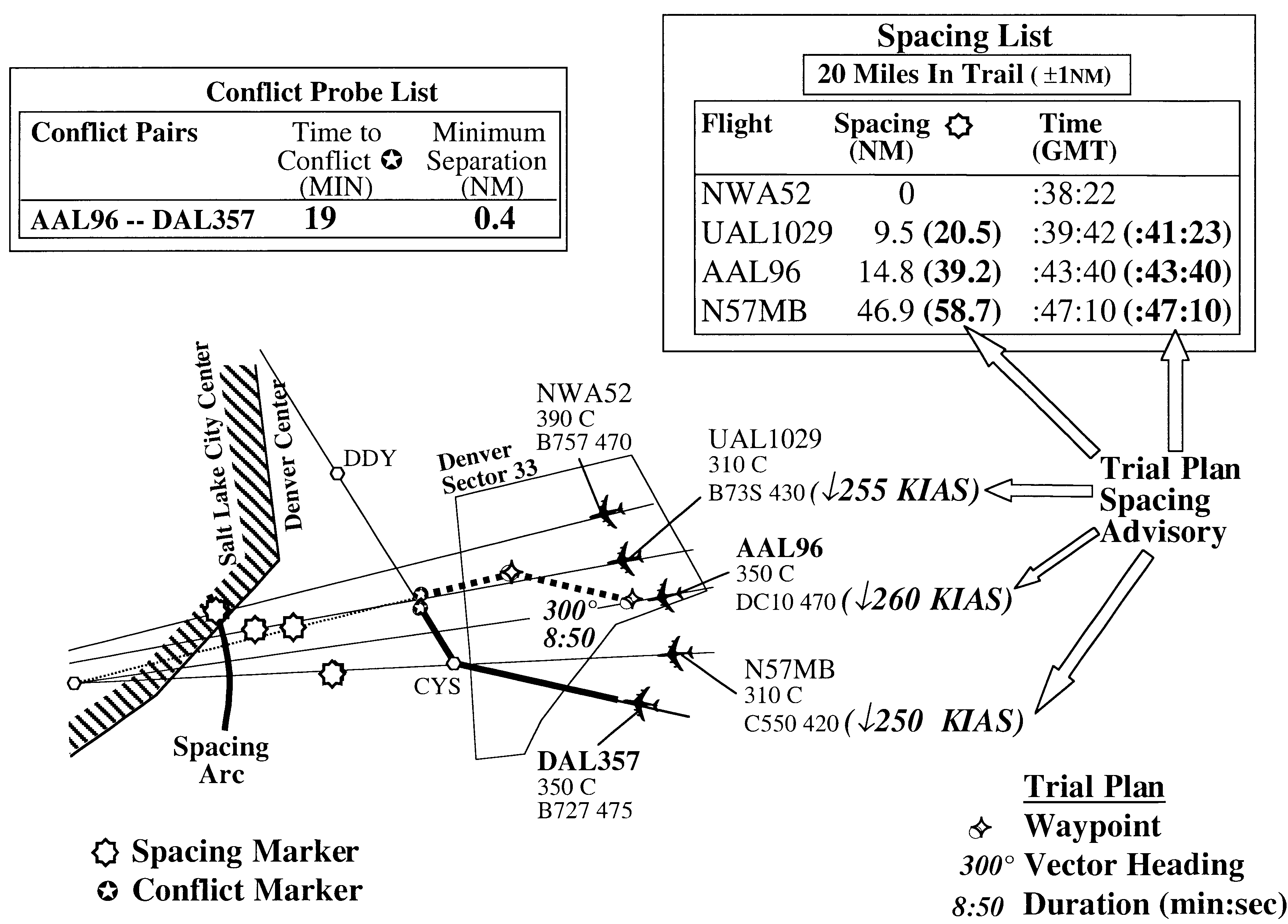
Referring to FIGS. 11-13, the following example scenario illustrates the integration of MIT-spacing conformance of the invention with conflict detection and resolution. The figures represent a simplified depiction of the tool's graphical interface from a 1996 version of CTAS. Note that the figures illustrate the spacing data in a tabular list, but the same data could also or instead be displayed on the aircraft's data tag. Providing an option to a controller permits the controller see all the data in one location even if aircraft are graphically located all over the display (or are off the display), or lets the controller see the data for each aircraft on the aircraft's tag which is located graphically where the aircraft position is.

To reiterate, the display of spacing-conformance analysis may be accomplished in a variety of ways depending on the operational considerations of the ATC facilities and controllers using the tool (or the operational limitations of the ATC computer / displa...


PUM


Abstract

A method of and computer software for minimizing aircraft deviations needed to comply with an en route miles-in-trail spacing requirement imposed during air traffic control operations via establishing a spacing reference geometry, predicting spatial locations of a plurality of aircraft at a predicted time of intersection of a path of a first of said plurality of aircraft with the spacing reference geometry, and determining spacing of each of the plurality of aircraft based on the predicted spatial locations.

Description

BACKGROUND OF INVENTION1. Field of the Invention (Technical Field)The present invention relates to en route spacing of aircraft.2. Description of the Prior ArtNote that the following discussion refers to a number of publications by author(s) and month and year of publication, and that due to recent publication dates certain publications are not to be considered as prior art vis-a-vis the present invention. Discussion of such publications herein is given for more complete background and is not to be construed as an admission that such publications are prior art for patentability determination purposes.En route miles-in-trail (MIT) spacing restrictions are often used to distribute arrival delays upstream of destination airports and to mitigate local areas of en route airspace congestion. National statistics for the U.S. indicate that en route spacing restrictions are applied for approximately 5000 hours per month. These restrictions impact approximately 45,000 flights per month. Curre...

Claims


Application Information

Patent Timeline
Patent Type & Authority Patents(United States)
IPC IPC(8): G01S13/00G01S13/91G01S7/04G01S7/22G08G5/00G08G5/04
CPCG01S7/22G08G5/0043G01S13/91
Inventor ERZBERGER, HEINZGREEN, STEVEN M.
Owner NAT AERONAUTICS & SPACE ADMINISTATION UNITED STATES OF AMERICA THE AS REPRESENTED BY THE SEC
Why Eureka
Try Eureka