Fuel injection valve

a fuel injection valve and valve body technology, applied in the direction of fuel injection apparatus, fuel feed system, spraying apparatus, etc., can solve the problems of difficult to obtain a large spray angle of fuel, manufacturing cost for forming such discharge orifices is significant, and the processing of the orifice plate becomes difficul

Inactive Publication Date: 2002-05-28
MITSUBISHI ELECTRIC CORP
View PDF15 Cites 66 Cited by
  • Summary
  • Abstract
  • Description
  • Claims
  • Application Information

AI Technical Summary

Problems solved by technology

Upstream of the orifice plate, fuel flows from the outer peripheral portion to the inner peripheral portion, so it is difficult to obtain a large spray angle for the fuel.
Furthermore, when manufacturing a one-spray type having a large spray angle (such as approximately 15 degrees or greater) or a two-spray type having a large spray angle (such as approximately 15 degrees or greater), it is necessary to make the angle of inclination of the discharge orifices 103 large, so it is difficult to form the discharge orifices so as to have a small diameter, and it is difficult and to make the diameter of the discharge orifices 103 small to obtain atomization of the fuel.
Even if discharge orifices 103 with a large angle of inclination and a small diameter can be formed, the manufacturing costs for forming such discharge orifices are significant.
This is especially the case with respect to an orifice plate having at least six discharge orifices 103 to promote atomization, since with such an orifice plate the diameter of the discharge orifices 103 becomes particularly small, so processing of the orifice plate becomes very difficult.
Furthermore, when L / .phi.d is made large, it becomes difficult to form the discharge orifices 103 in the orifice plate, and increasing the angle of inclination of the discharge orifices 103 increases the difficulty of forming the discharge orifices in the orifice plate, resulting in extreme increases in manufacturing costs.
Such an orifice plate is extremely expensive to manufacture.

Method used


Image

  • Fuel injection valve
  • Fuel injection valve
  • Fuel injection valve

Examples


first embodiment

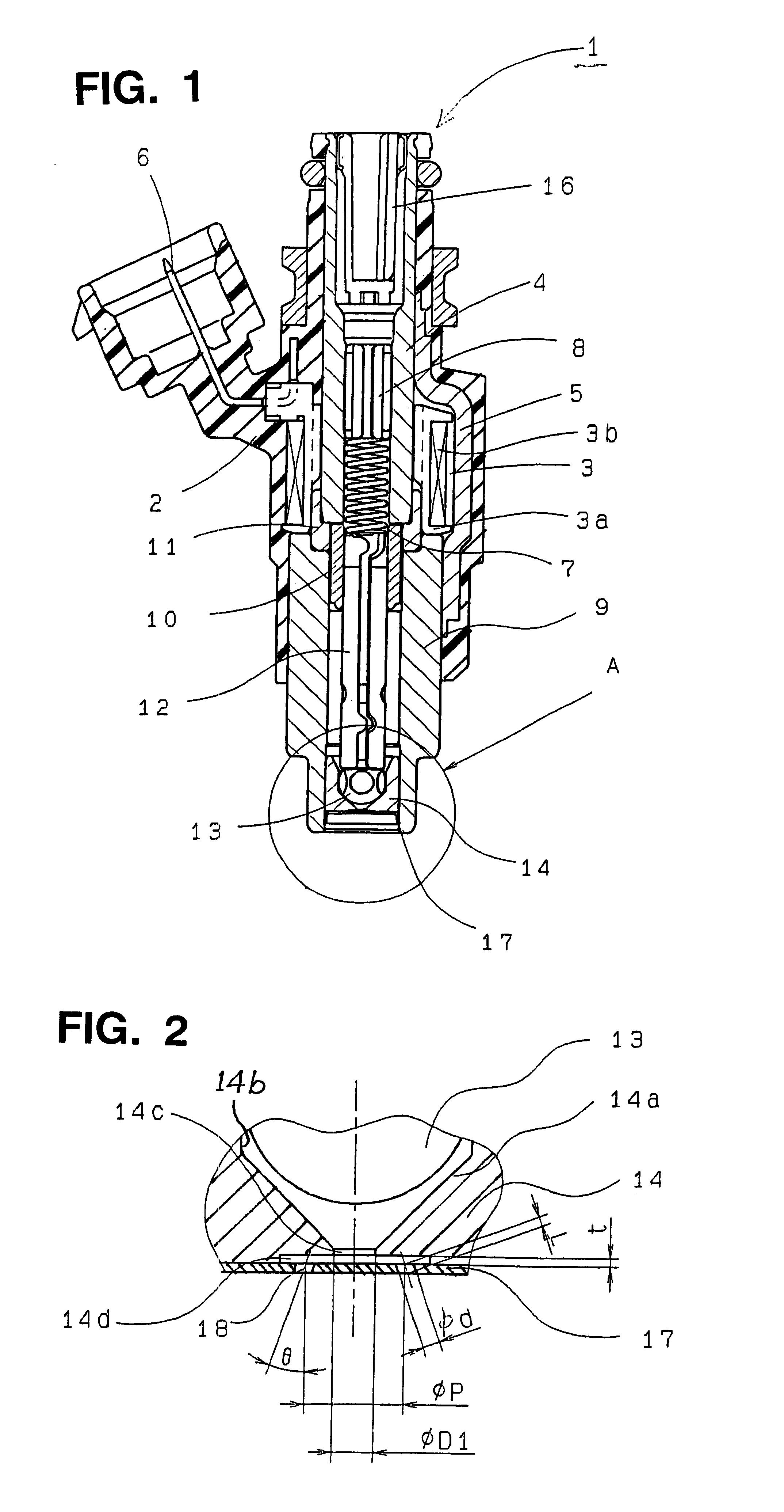
A number of preferred embodiments of a fuel injection valve according to the present invention will be described while referring to the accompanying drawings. FIG. 1 is a cross-sectional elevation of a fuel injection valve 1 according to the present invention. The fuel injection valve 1 includes an electromagnetic coil 3, a stationary ferromagnetic core 4, and metal plates 5 defining a magnetic path, all disposed in a resin housing 2. The electromagnetic coil assembly 3 includes a resin bobbin 3a, a coil 3b which is wound around the outer periphery of the bobbin 3a, and a terminal 6 which is electrically connected to the coil 3b and which enables the coil 3b to be electrically connected to an external source of electric power. The resin housing 2 is molded around the electromagnetic coil assembly 3.

An adjuster 8 which adjusts the load of a compression spring 7 is secured inside the fixed core 4. Two metal plates 5 (only on of which is shown) which form a magnetic path each have one ...

second embodiment

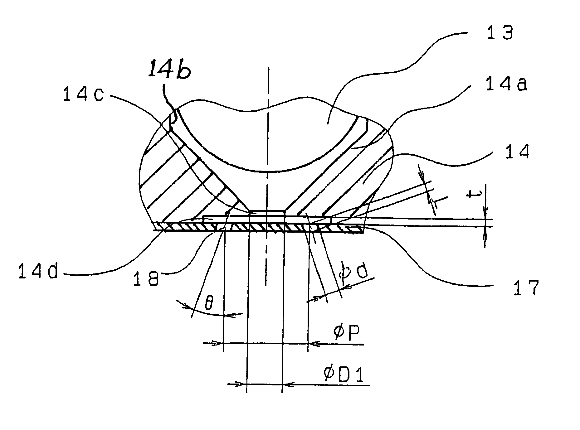
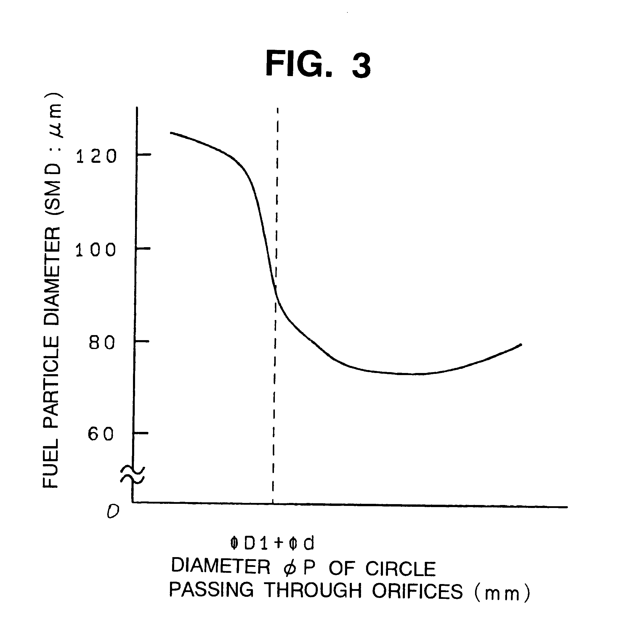
FIG. 4 is a schematic perspective view of the lower end of a fuel injection valve according to the present invention. In this embodiment, the atomization of fuel in the fuel injection valve is further promoted by not only satisfying the above-described inequalities .phi.D1+.phi.d<.phi.P and t<.phi.d but by also selecting the overall cross-sectional area S1 of the discharge orifices 18 so as to satisfy a prescribed relationship. In this embodiment, the ratio S2 / S1 of the surface area S2 of an imaginary cylindrical surface extending from the cylindrical fuel passage 14c as shown in FIG. 4 and the total cross-sectional area S1 of the discharge orifices 18 (which is the sum of the cross-sectional areas of the individual discharge orifices 18 provided in the orifice plate 17) is made to satisfy the inequality 1


PUM


Abstract

A fuel injection valve includes an orifice plate having a plurality of discharge orifices formed therein. A valve seat is disposed upstream of the discharge orifices and has a cylindrical fuel passage formed therein. A fuel cavity is formed between the cylindrical fuel passage and the orifice plate directly above the discharge orifices. A valve member is supported for reciprocating movement into and out of contact with the valve seat. The fuel injection valve satisfies the inequalitieswherein phiD1 is the diameter of the cylindrical fuel passage, phid is the diameter of each discharge orifice, phiP is the diameter of an imaginary circle passing through the center of each discharge orifice, and t is the depth in the axial direction of the fuel cavity.

Description

REFERENCE TO RELATED APPLICATIONSThis application is based on Japanese Patent Application No. 2000-221643, filed in Japan on Jul. 24, 2000, the contents of which are hereby incorporated by reference.1. Field of the InventionThis invention relates to a fuel injection valve for an internal combustion engine.2. Description of the Related ArtFuel injection valves are widely used to supply fuel to internal combustion engines. One example of a known fuel injection valve for use with an internal combustion engine is disclosed in Japanese Published Unexamined Patent Application Hei 9-14090. FIG. 6 is a cross-sectional elevation of a fuel injection valve disclosed in that publication, and FIG. 7 is an enlarged view of the lower end of the fuel injection valve of FIG. 6.The illustrated fuel injection valve 1 includes an electromagnetic coil 3, a stationary ferromagnetic core 4, and metal plates 5 defining a magnetic path, all disposed in a resin housing 2. The electromagnetic coil assembly 3 ...

Claims


Application Information

Patent Timeline
Patent Type & Authority Patents(United States)
IPC IPC(8): F02M61/18F02M61/00F02M51/06
CPCF02M61/1853F02M51/0682F02M51/0678Y10S239/90F02M61/18
Inventor MUNEZANE, TSUYOSHISUMIDA, MAMORU
Owner MITSUBISHI ELECTRIC CORP
Why Eureka
Try Eureka