Additionally, the
nozzle tip member does not define a contained environment where "compression" of the filler material takes place through the
mask followed by the immediate shearing off of the filler material within that contained environment from the surface of the stencil.
In fact, the
nozzle tip member itself provides no effective means for shearing off filler material from the top of the stencil, rather, after the through hole is filled and filler material "backs up" through the stencil, the
nozzle tip member moves forward whereupon the "excessive" filler material is then wiped off by a separate, single, flexible squeegee member which is designed for unidirectional use only.
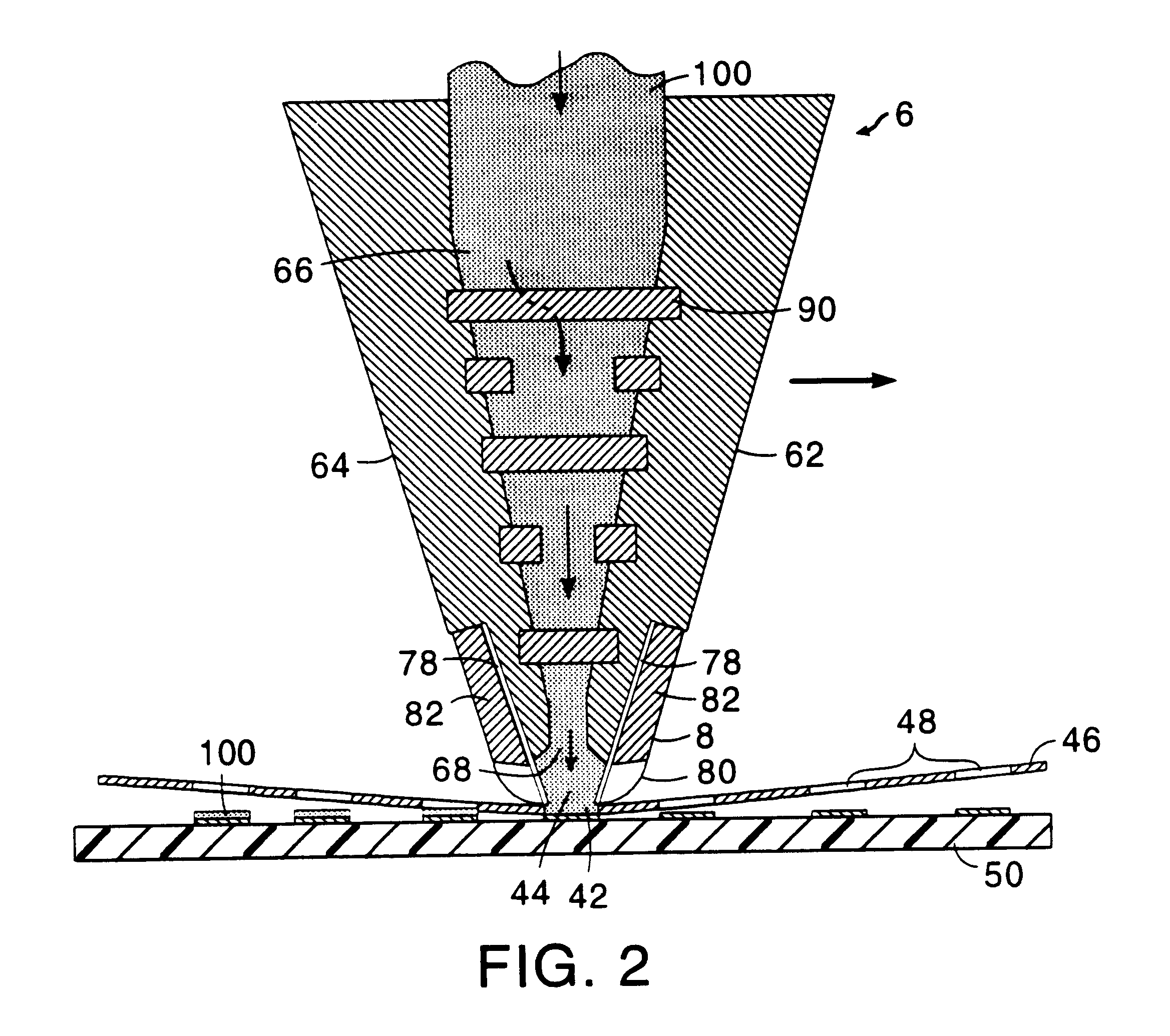
Unfortunately, these conventional efforts do not provide a contained environment for compression of viscous material through holes in a stencil and shearing of viscous material within the contained environment from the upper surface of the stencil.
Reliance upon squeegee movement to force the viscous material, such as solder paste, through the stencil openings can lead to damage and eventual failure of both the squeegee blades and the stencil due to repeated friction.
Since conventional efforts do not provide a contained environment in which compression and shearing is accomplished, waste of the viscous material is frequently encountered.
Conventional efforts, therefore, (1) fail to maximize the efficiency of printing solder paste onto a desired area of a printed wiring board and (2) fail to minimize waste of the solder paste during the printing process.
Moreover, these conventional methodologies and assemblies do not substantially ensure that the viscous material is dispensed and selectively placed upon the various portions of the circuit board, through the perforated stencil, at a substantially equal velocity.
These conventional methodologies and assemblies also do not substantially ensure that the "backpressure" formed within the compression head and / or within or through those portions of the exit aperture overlaying
solid or "non-perforated" portions of the stencil and / or overlaying those perforated stencil portions which are filled with paste or viscous material, is substantially identical or uniform.
Hence, these conventional methodologies and assemblies provide an undesirable and "non-uniform" velocity and pressure or "backpressure" distribution or "profile".
This non-uniform velocity and pressure distribution or profile causes uneven amounts of the viscous material to be deposited upon the stencil, thereby causing much of the deposited paste or viscous material to be undesirably wasted and concomitantly reducing the overall quality of the printed and created circuit board.
While these plates or islands do reduce some of the foregoing non-uniformity, they suffer from some drawbacks.
By way of example and without limitation, the use of these plates and / or islands requires that a relatively costly and time-consuming modification of the compression head be made (e.g. the compression head must be "opened" and these objects must be securely fitted or positioned within the head).
These plates or islands further cause relatively large pressure losses to occur within the compression head, thereby requiring the viscous material to be communicated to the compression head at a relatively
high pressure.
This relatively "
high pressure injection" arrangement causes the creation of significant amounts of "
back pressure" within the compression head.
Particularly, this undesirably created "large amount of
back pressure" frequently causes the wiper blades to undesirably "lift up" or become disengaged from the surface of the stencil, thereby preventing the blades from properly wiping the stencil of the selectively deposited viscous material and causing circuit boards of an unacceptably
poor quality to be created.
Further, this required
high pressure, in combination with certain "stagnation regions" within the compression head which are generally located between the various perforations or openings in the diffuser plates or islands, causes compaction of the received viscous material and deposition onto the
diffusion plates or islands, thereby undesirably "clogging" the flow path and requiring frequent and
time consuming maintenance and cleaning of the deployed plates / islands.

