Novel water turbine generator set
A technology of generating sets and water turbines, which is applied in hydroelectric power generation, machines/engines, mechanical equipment, etc., and can solve problems such as large impact, easy damage to equipment, and large impact force of devices
- Summary
- Abstract
- Description
- Claims
- Application Information
AI Technical Summary
Problems solved by technology
Method used
Image
Examples
Embodiment 1
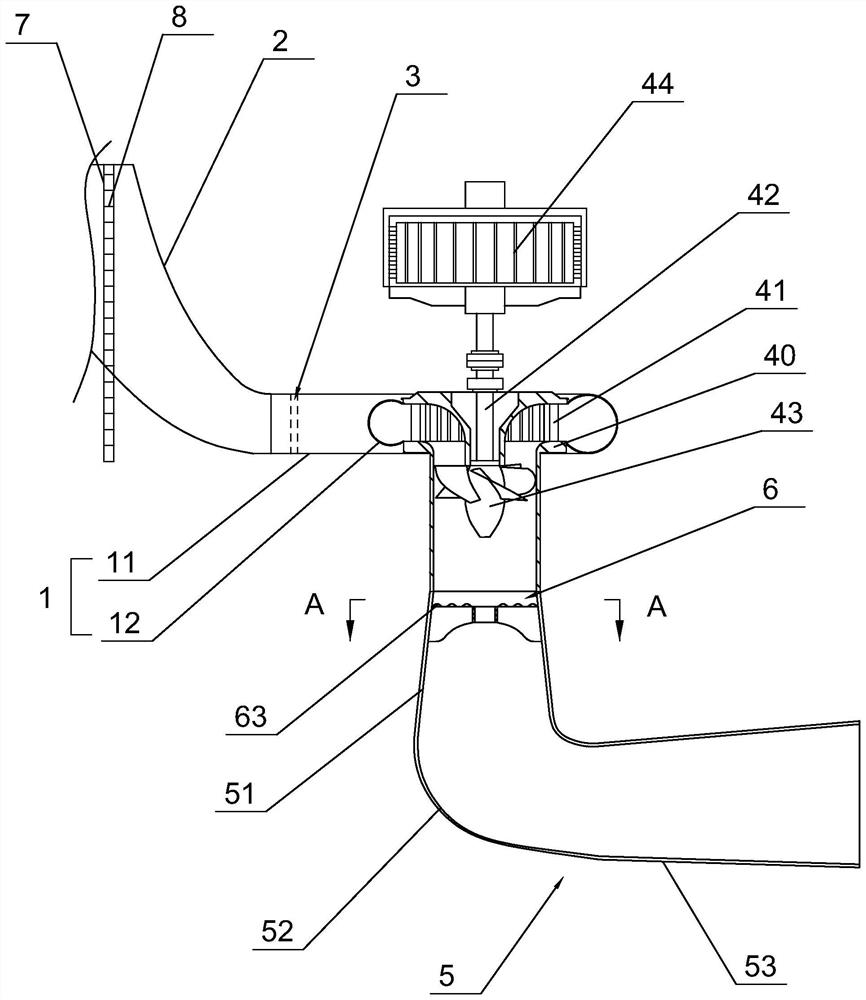
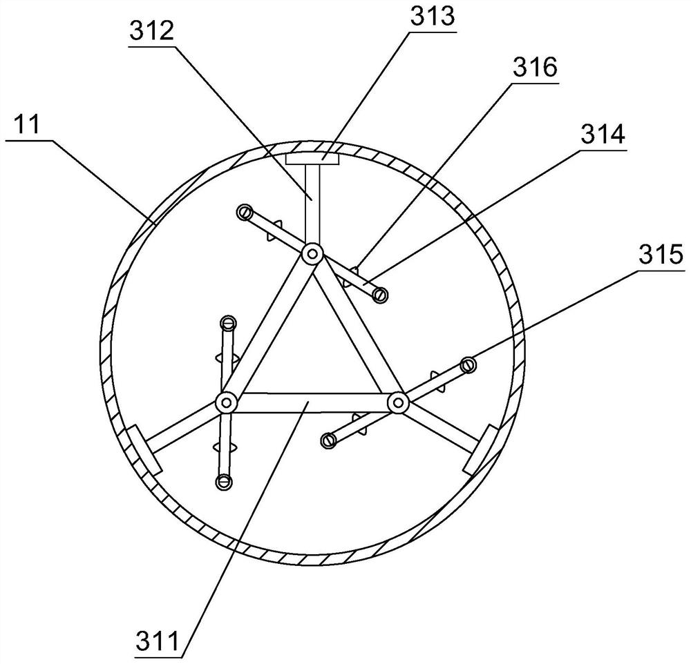
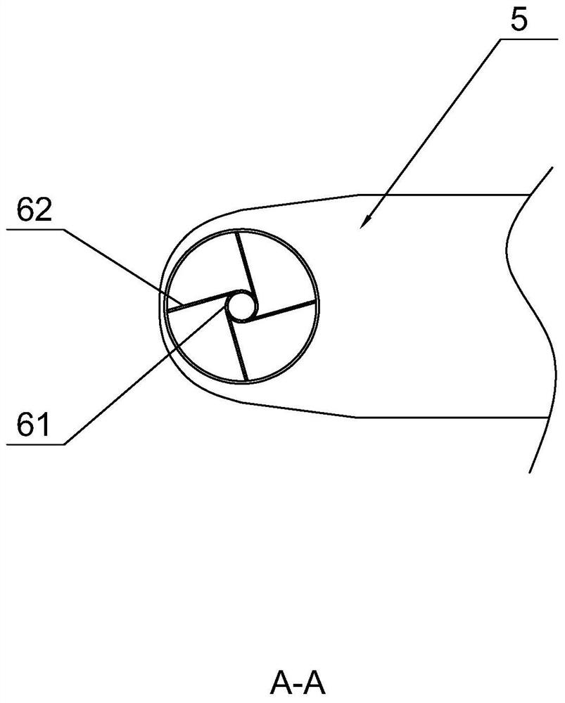
[0047] refer to figure 1 , is a new type of hydraulic turbine generator set disclosed by the present invention, comprising a volute 1, the volute 1 is composed of a fixed-diameter straight cylinder section 11 and a variable-diameter helical section 12 connected to each other, and one end of the fixed-diameter straight cylinder section 11 is provided with a water inlet. A water diversion pipe 2 is connected to the water inlet, and the inlet of the water diversion pipe 2 is connected to the upstream water level. The circumference of the water diversion pipe 2 gradually decreases from top to bottom, thereby increasing the potential energy of the water flow. The end of the fixed-diameter straight cylinder section 11 close to the water diversion pipe 2 is provided with a water inlet stabilizing device 3 to reduce the influence of the water inlet pulsating pressure on the entire unit. A ring seat 40 communicating with it is fixed at the center of the variable-diameter helical sectio...
Embodiment 2
[0061] refer to Figure 4 with Figure 5 , the difference from Embodiment 1 is that the water inlet stabilizing device 3 is a fixed straight-through type stabilizing device, and the fixed straight-through type stabilizing device includes an annular bracket 321 fixedly connected to the inner wall of the straight cylinder section 11 with a fixed diameter, and the annular bracket 321 can be A spoiler 322 is disassembled and connected, and a plurality of spoiler holes 323 are opened on the spoiler 322. The axis of the spoiler hole 323 and the axis of the fixed-diameter straight cylinder section 11 are parallel to each other, and the respective spoiler holes 323 are arranged at equal intervals. The inner side of the spoiler hole 323 is curved to form a butterfly-shaped drain, and the diameter of the spoiler hole 323 gradually decreases along the water flow direction. An annular groove 324 is defined inside the annular bracket 321 along its radial direction, and the spoiler 322 is ...
PUM
 Abstract
Description
Claims
Application Information
 - R&D
- Intellectual Property
- Life Sciences
- Materials
- Tech Scout
- Unparalleled Data Quality
- Higher Quality Content
- 60% Fewer Hallucinations
Browse by: Latest US Patents, China's latest patents, Technical Efficacy Thesaurus, Application Domain, Technology Topic, Popular Technical Reports.
© 2025 PatSnap. All rights reserved.Legal|Privacy policy|Modern Slavery Act Transparency Statement|Sitemap|About US| Contact US: help@patsnap.com


