Line fiber for WDM optical fiber transmission systems

a transmission system and optical fiber technology, applied in the direction of optical fiber with multi-layer core/cladding, optical waveguide light guide, instruments, etc., can solve the problems of difficult operation of the transmission system under realistic conditions, high cost of fiber, and configuration suffers from the drawback of cost nearly double, so as to increase the channel data rate and keep the system cost down.

Inactive Publication Date: 2002-05-28
DRAKA COMTEQ BV
View PDF6 Cites 90 Cited by
  • Summary
  • Abstract
  • Description
  • Claims
  • Application Information

AI Technical Summary

Benefits of technology

The invention proposes a solution to this new problem. More generally, the invention provides a solution to the problem of increasing channel data rate in WDM transmission systems; the solution

Problems solved by technology

That solution suffers from the drawback of allowing only small power margins to be used, thereby making it difficult to operate the transmission system under realistic conditions, in particular for WDM transmission systems having a large number of channels.
A drawback of that of fiber is its high cost.
Nevertheless, that configuration suffers from the drawback of cost that

Method used


Image

  • Line fiber for WDM optical fiber transmission systems
  • Line fiber for WDM optical fiber transmission systems
  • Line fiber for WDM optical fiber transmission systems

Examples


first embodiment

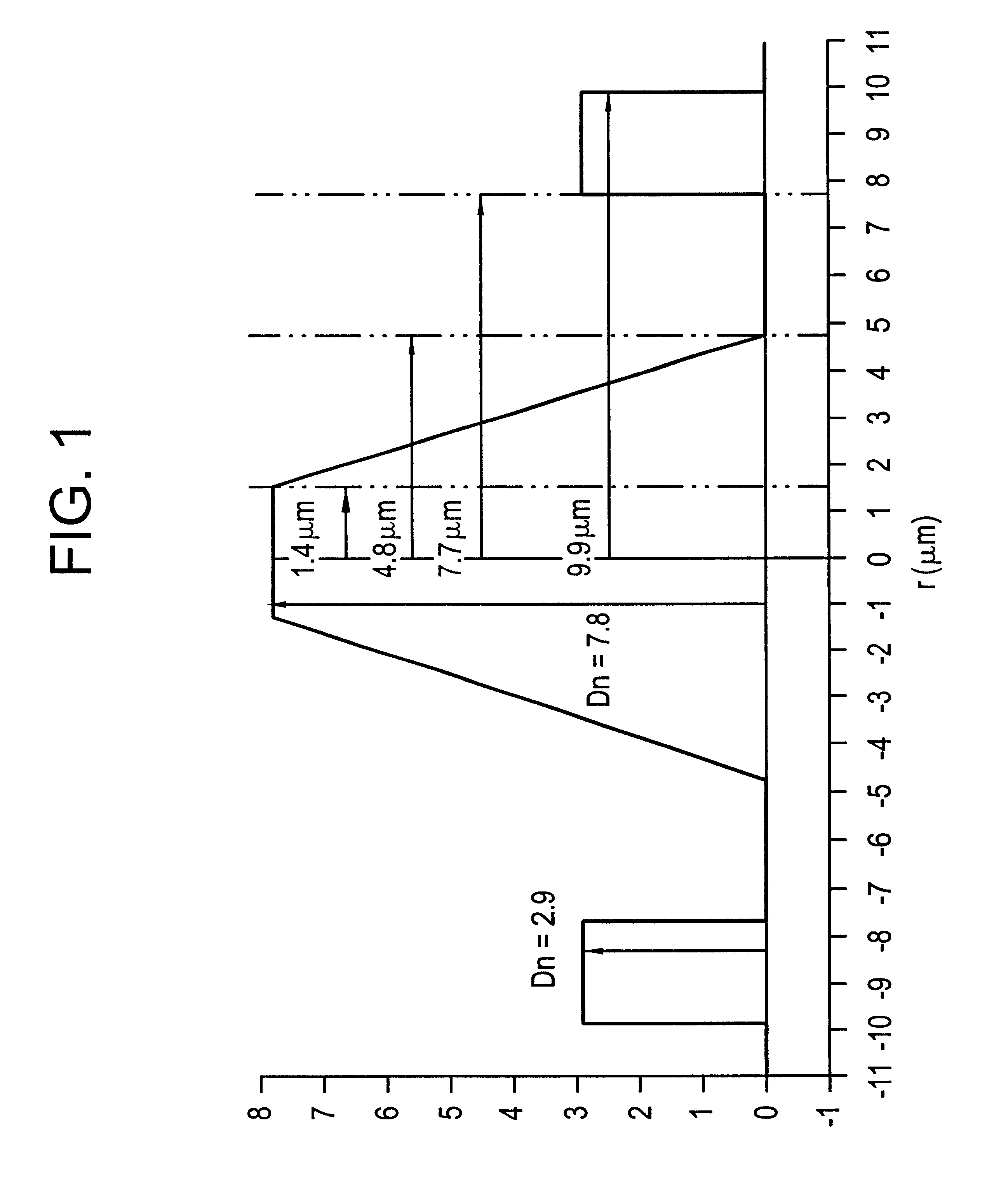
FIG. 1 is a diagram of the index profile of a fiber constituting the invention; in this embodiment, the index profile is a trapezoid type index profile with a ring, and it presents, starting from the center of the fiber:

a central portion having a refractive index greater than that of the cladding; and

a first annular portion in which the index decreases in substantially linear manner;

the fiber as a whole constituting a fiber having a so-called "trapezoid" profile.

Around this first annular portion, the fiber has a portion of substantially constant index, followed by a second annular portion of index greater than that of the cladding, forming a ring about the trapezoid profile.

The values for the indices and the radii in the embodiment of FIG. 1 are as follows. The central portion has a radius r.sub.1 of 1.4 .mu.m and its index differs from the index of the cladding by .DELTA.n.sub.1 equal to 7.8.times.10.sup.-3.

The index decreases in substantially linear manner to go from the value .DE...

second embodiment

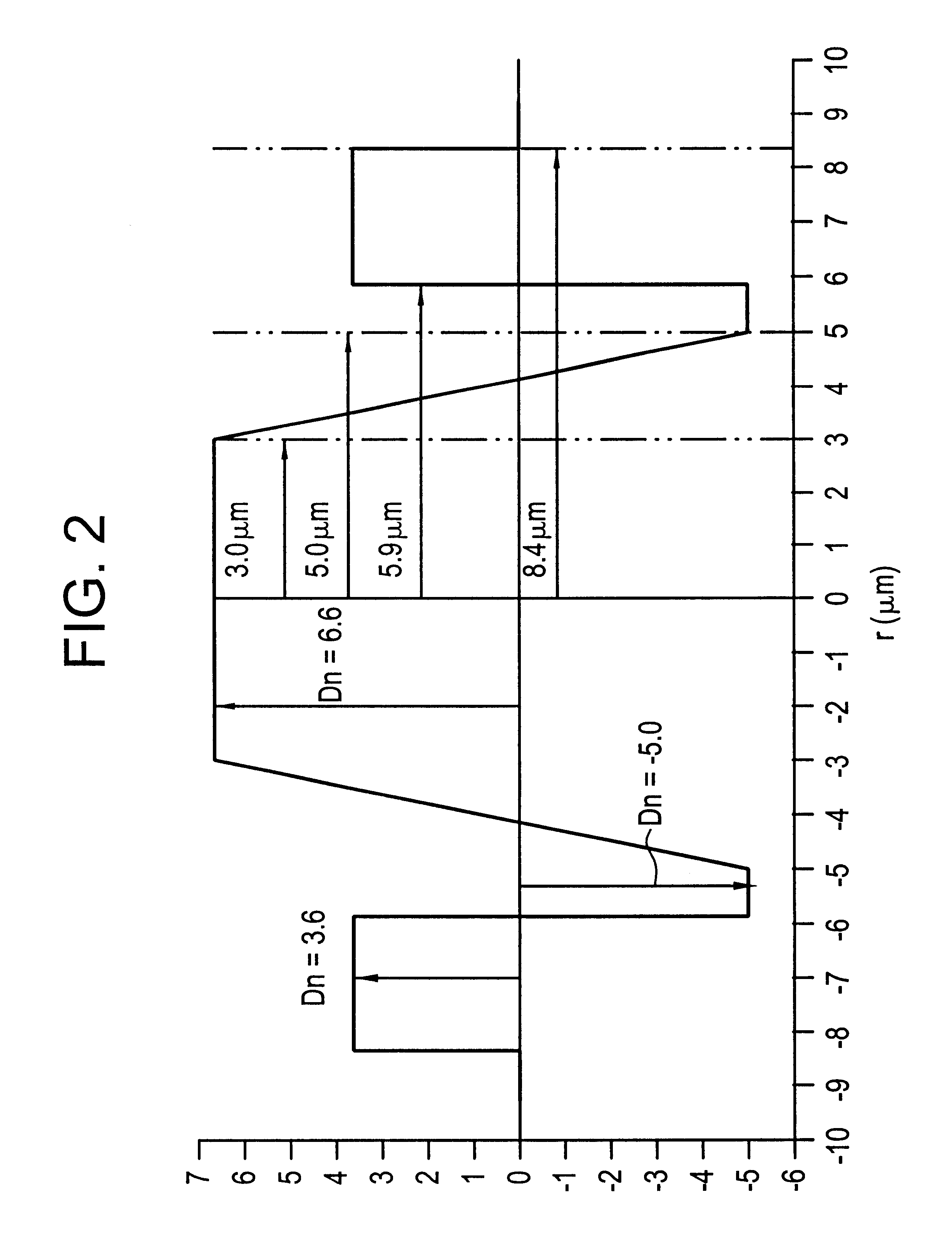
FIG. 2 is a diagram of the index profile of a fiber constituting the invention. In this embodiment, the index profile is a trapezoid type index profile having buried cladding with a ring. In other words, compared with the profile of FIG. 1, the substantially constant index portion surrounding the trapezoid has an index smaller than the index of the fiber cladding. The profile of FIG. 2 is described using the same notation as used for FIG. 1 concerning radii and indices.

The geometrical characteristics of the profile of FIG. 2 are as follows:

r.sub.1 =3.0 .mu.m

r.sub.2 =5.0 .mu.m

r.sub.3 =5.9 .mu.m

r.sub.4 =8.4 .mu.m

.DELTA.n.sub.1 =6.6

.DELTA.n.sub.3 =-5.0

.DELTA.n.sub.4 =3.6

These values make it possible to obtain a fiber having the following characteristics:

a theoretical cutoff wavelength .lambda..sub.cth : 1620 nm;

a chromatic dispersion canceling wavelength .lambda..sub.0 : 1410 nm;

chromatic dispersion slope at 1550 nm: 0.055 ps / (nm.sup.2.km);

chromatic dispersion at 1550 nm: 8 ps / (nm.km);...

sixth embodiment

FIG. 6 is a diagram showing the index profile of a fiber constituting the invention. The profile of FIG. 6 is a coaxial profile, surrounded by a buried portion. Starting from the center, the fiber has:

a central portion of substantially constant index;

an annular portion of index greater than the index of the cladding, and also greater than the index of the central portion; and

a buried portion of index smaller than the index of the cladding.

The index and radius values given in the embodiment of FIG. 6 are as follows. The central portion has a radius r.sub.1 of 2.4 .mu.m and its index differs from the index of the cladding by .DELTA.n.sub.1 =-5.9.times.10.sup.-3.

The annular portion extends between the radius r.sub.1 and the radius r.sub.2 =5.3 .mu.m, and its index differs from that of the cladding by .DELTA.n.sub.2 =9.2.times.10.sup.-3.

The buried portion extends from radius r.sub.2 to radius r.sub.3 =8.4 .mu.m. Compared with the index of the cladding, its index differs by .DELTA.n.sub....


PUM


Abstract

The invention provides a monomode optical fiber having, at a wavelength of 1550 nm: an effective section area greater than or equal to 60 mum2; chromatic dispersion close to 8 ps/(nm.km); a chromatic dispersion slope of absolute value less than 0.07 ps/(nm2.km). In the range of wavelengths used in a WDM transmission system, typically 1530 nm to 1620 nm, the fiber has chromatic dispersions greater than 7 ps/(nm.km), thereby making it possible to limit non-linear effects. The invention also provides a WDM optical fiber transmission system using such a fiber as a line fiber. The small slope of its chromatic dispersion is an advantage in such a system.

Description

The present invention relates to the field of transmission by optical fiber, and more particularly to the field of transmission by wavelength division multiplexing (WDM) using a dispersion-shifted line fiber.For optical fibers, the index profile is generally described as a function of the appearance of a graph showing refractive index as a function of fiber radius. Conventionally, distance r from the center of the fiber is plotted along the abscissa, and the difference between the refractive index and the refractive index of the cladding of the fiber is plotted up the ordinate. Index profiles are thus said to be "stepped", "trapezoid", or "triangular" for graphs that are respectively stepped, trapezoid, or triangular in shape. These curves are generally representative of the theoretical or ideal profile of the fiber, since constraints associated with manufacturing the fiber can lead to a profile that is significantly different.In new very high data rate transmission networks that ar...

Claims


Application Information

Patent Timeline
IPC IPC(8): G02B6/02G02B6/036
CPCG02B6/02014G02B6/02242G02B6/02271G02B6/03644G02B6/03611G02B6/03627G02B6/0281
Inventor DE MONTMORILLON, LOUIS-ANNENOUCHI, PASCALEROUSSEAU, JEAN-CLAUDESAUVAGEON, RAPHAELLECHARIOT, JEAN-FRAN.CEDILLA.OISBERTAINA, ALAIN
Owner DRAKA COMTEQ BV
Why Eureka
Try Eureka