Circuit arrangement for monitoring an electronic switch controlling a load

a technology of electronic switches and circuit arrangements, which is applied in the direction of emergency protective arrangements for limiting excess voltage/current, circuit interrupter testing, and base element modifications, etc., can solve the problems of insufficient control and monitoring, no longer economical solution above a certain current value, and inability to integrate the shunt resistor into the drive elemen

Inactive Publication Date: 2002-06-04
MELCHER ROLF +1
View PDF16 Cites 61 Cited by
  • Summary
  • Abstract
  • Description
  • Claims
  • Application Information

AI Technical Summary

Problems solved by technology

With high load currents, it is not economic to integrate the shunt resistor into the drive element.
However, a drawback to the above is that the power MOSFETs are produced in a rather complex process technology when compared with discrete transistors so that this solution is no longer economical above a certain current value.
Since the turn-on resistance of a transistor is subject to a relatively large variance in components, temperature dependence, and degradation with age, this measure is very inexact so that it is insufficient for a control and monitoring of a motor bridge circuit, for example.
Calibration methods based on calibration curves of the turn-on resistance as a function of the temperature

Method used


Image

  • Circuit arrangement for monitoring an electronic switch controlling a load
  • Circuit arrangement for monitoring an electronic switch controlling a load
  • Circuit arrangement for monitoring an electronic switch controlling a load

Examples


Embodiment Construction

with reference to the accompanying figures, wherein:

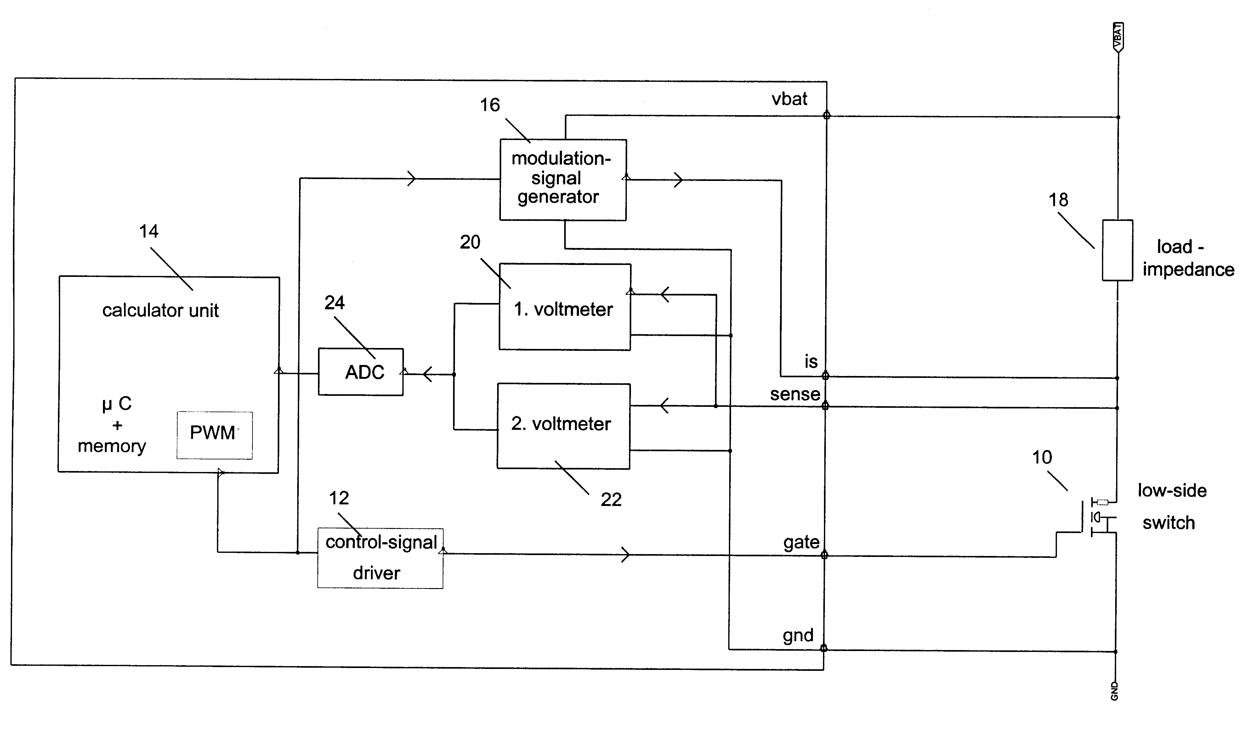
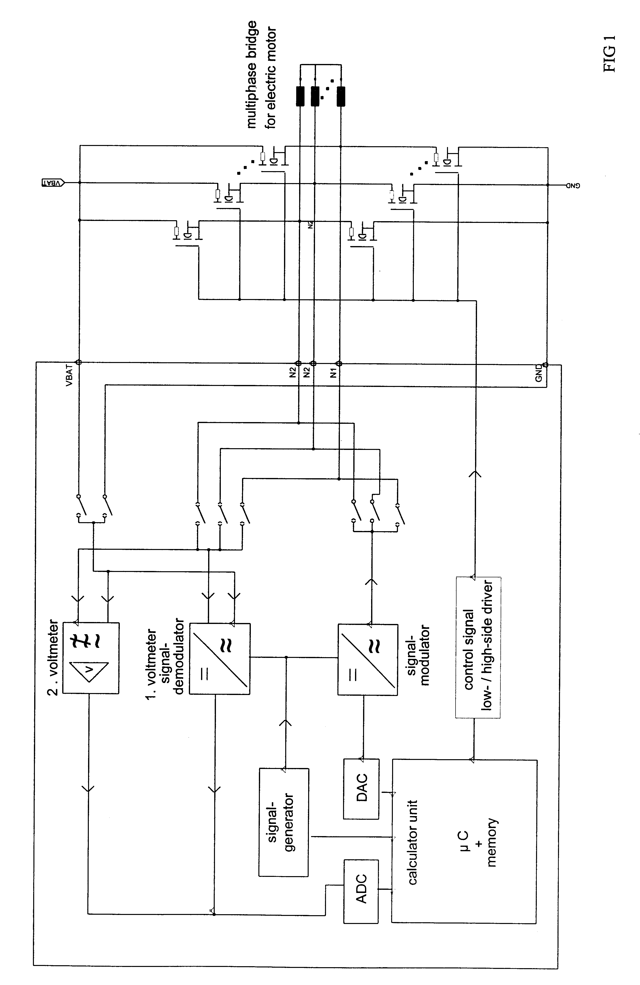
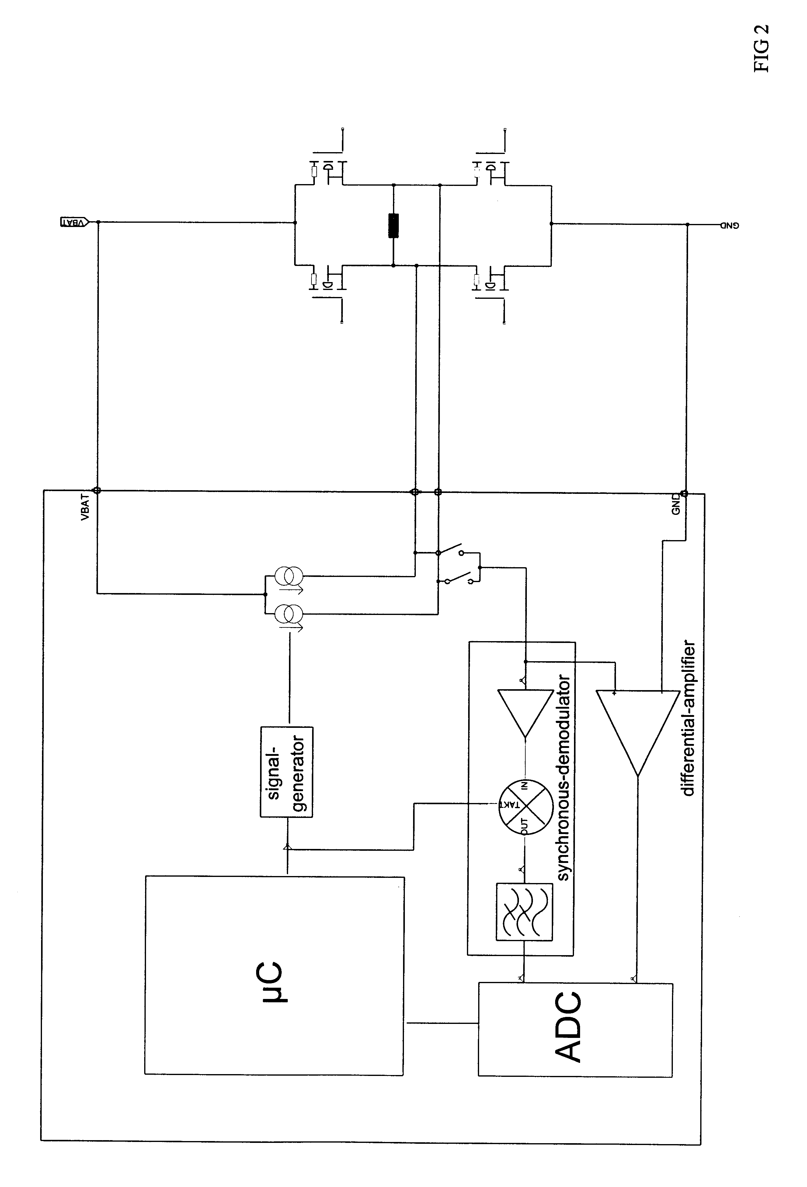
FIGS. 1 and 2 illustrate embodiments of the invented circuit arrangement implemented for monitoring the high and low side switches of a motor bridge control circuit;

FIGS. 3 and 4 illustrate embodiments of the invented circuit arrangement implemented as electronic switches acting as high side and low side switches;

FIGS. 5 and 6 illustrate embodiments of the invented circuit arrangement according to FIGS. 3 and 4, comprising an analogue evaluation unit instead of a micro-controller; and

FIG. 7 illustrates embodiments of the invented circuit arrangement implemented for monitoring and controlling switches and loads comprising a load impedance correction algorithm to achieve higher accuracies.

Referring now to FIGS. 1 and 2, an exemplary embodiment of the present invention comprises a current modulator and a synchronous voltage modulation for realizing the functions according to the invention. As illustrated in FIGS. 1 and 2, the measurin...


PUM


Abstract

In a circuit arrangement for monitoring an electronic switch provided for controlling a load and current flown through the load during turn-on intervals for driving the load, the switch has a substantially linear resistance behavior during parts of its turn-on state and the operating point of the switch is located in this part of the turn-on state during the load control. The circuit arrangement comprises a modulation signal generator for generating a modulation signal for modulating the load current flowing through the electronic switch. A first voltage measuring device measures the first voltage drop across the electronic switch caused by the modulation signal. A second voltage measuring device measures the voltage drop across the electronic switch caused by the load current, and an evaluation unit determines the load current from the modulation signal and the first and second voltage drops.

Description

1. Field of the InventionThe present invention relates to a monitoring and current measuring unit for MOSFET transistors in low side (LS) and / or high side (HS) configuration, with any electrical load, in particular, an inductive load. The invention is aimed at a precise detection of a current through a transistor and at the detection of faulty conditions by only observing the voltage curve of the drain-to-source voltage of a HS and a LS transistor for driving a load.2. Description of Related ArtConventionally, to realize the functionality described, a measuring method is frequently used for load drives with discrete power MOSFETs, such a method is based on measuring current across a shunt resistor in the load current circuit (see, e.g., U.S. Pat. No. 4,967,309 and U.S. Pat. No. 4,820, 968). At present, these discrete power MOSFETs are driven by ICs based on high voltage BCD and CMOS process technologies. With high load currents, it is not economic to integrate the shunt resistor int...

Claims


Application Information

Patent Timeline
IPC IPC(8): G01R31/327H03K17/082
CPCG01R31/3277H03K17/0822
Inventor MELCHER, ROLFSELIGER, SIEGFRIED
Owner MELCHER ROLF
Why Eureka
Try Eureka