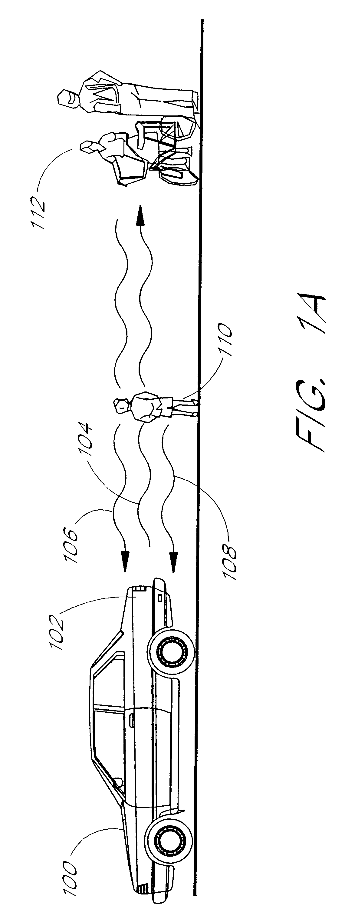
Many lane-change collisions occur because a driver of a first vehicle desiring to change lanes does not see a second vehicle in an adjacent lane, especially when the front bumper of the second vehicle is beside the rear portion of the first vehicle.
Yet, in
spite of the obvious desirability, and decades of research, automotive warning radars have not been widely used.
To date,
automotive radar warning systems have been either too primitive to provide useful information to the driver, or too expensive.
Those radars that do provide downrange information typically do not provide accurate downrange information for multiple targets because the radars cannot discriminate between multiple targets.
Radars that do attempt to discriminate between multiple targets are generally too costly for most drivers to afford.
Unfortunately, this type of radar provides no downrange information, and so the driver does not know how close the object is to the vehicle.
Unfortunately, the two-frequency CW radar performs poorly when there are multiple targets within the
field of view of the radar.
The simple two frequency system cannot discriminate between two targets at different ranges and thus, the range measurements obtained from a two frequency CW system in the presence of multiple targets is unreliable.
However, UWB radars are undesirable because these radars transmit energy over very wide bandwidths and create
electromagnetic interference which can interfere with other
radio frequency systems such as broadcast radio, television, cellular phones, etc.
These very
broad band antennas can be difficult to design and build.
Additional problems arise when mounting
backup warning radars to large trucks, delivery vans, construction vehicles, and semi-trailers, etc.
Existing backup warning systems and lane-change aids for trucks are expensive and difficult to retrofit into existing
truck fleets.
Installation of the radar units requires skilled personnel and several hours to install.
This may be especially problematic when the owner of a large fleet of trucks desires to
upgrade some or all of the fleet with backup warning radars.
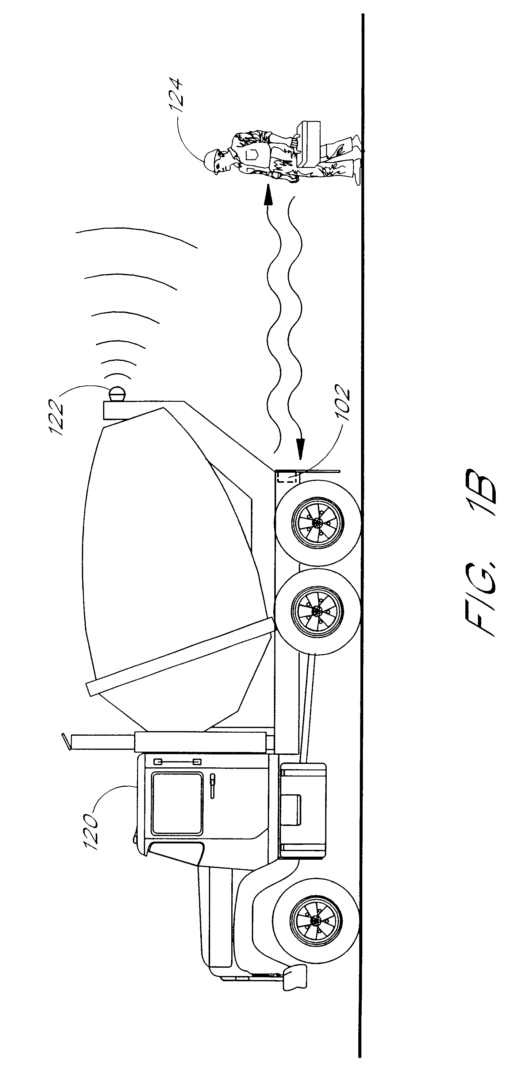
However, experience has shown that in a noisy construction site with many warning devices 122, workers begin to ignore the warning sound and thus accidents involving vehicles backing over workers still occur.
Furthermore, the warning device 122 is only effective against people since the driver of the vehicle 120 may still back into an inanimate object.
For example, if the radar 102 is so sensitive that it sounds a
false alarm every time the vehicle 100 or 120 moves backwards, then the driver of the vehicle will quickly learn to ignore the warning and the effectiveness of the warning is lost.
Conversely, if the radar 102 is made so insensitive that it does not sound an alarm in time, then again, the effectiveness of the warning is lost.
Limiting the downrange
field of view is a rather crude solution which denies the driver much of the information needed to avoid a collision in a real-world environment.
However, in some circumstances, installation of the radar sensor 202 may be difficult or costly.
Thus, the
control unit 1402 may not be able to perform certain configuration, reliability, and maintenance functions involving the radar sensors until the reverse switch is activated.
Thus, even though the
brake lights may not be used as much as the running lights, operation of the
brake lights can produce a significant heat rise in the housing 1502.
This temperature will cause the temperature of
electronic equipment, such as the radar circuit board 1516, to rise and thereby possibly adversely affect the operation of the radar sensor.
Advantageously, the LEDs have a much longer useful life than an incandescent lamp.
The power supplied to the V+ input 1501 is often "dirty" power containing engine
noise,
voltage spikes, current spikes, etc.
However, the
data processing and communication requirements in a digital system can become unwieldy if measures are not taken to control the amount of data produced.
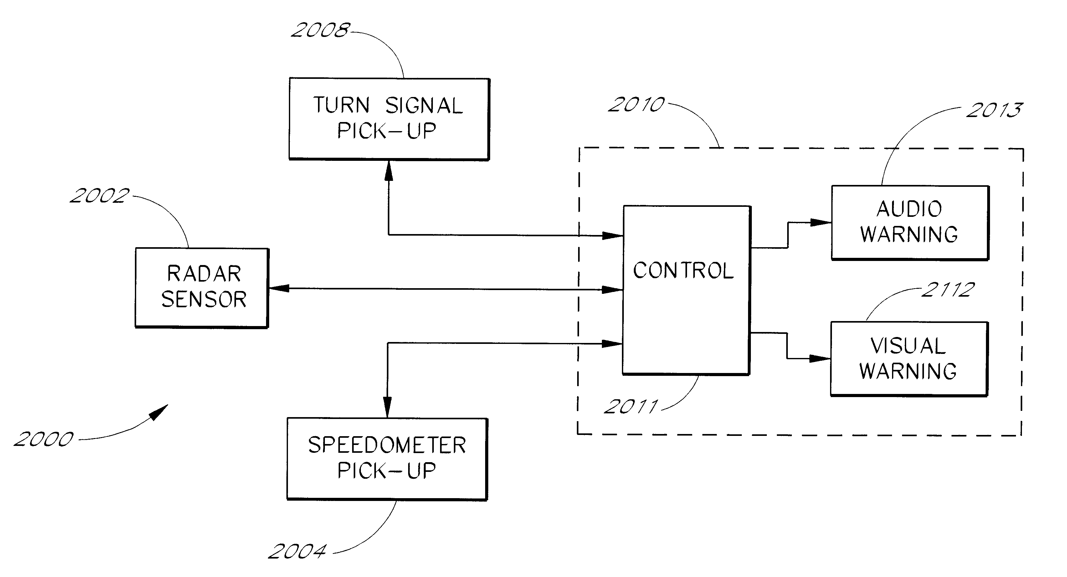
However, in order to avoid annoying the driver, the audible warning devices are typically only active when the driver is actually trying to change lanes and the radar detects a vehicle in the adjacent lane.

