Auto-ignition combustion management in internal combustion engine

a technology of internal combustion engine and combustion management, which is applied in the direction of combustion engine, electric control, machines/engines, etc., can solve the problems of increased nox production, limited range at which an engine can be operated with a lean air/fuel mixture, and increased cylinder pressure. , to achieve the effect of increasing the production of nox, and limiting the operation range of the engin

Inactive Publication Date: 2002-06-11
NISSAN MOTOR CO LTD
View PDF12 Cites 43 Cited by
  • Summary
  • Abstract
  • Description
  • Claims
  • Application Information

AI Technical Summary

Benefits of technology

a control arrangement being such that said fuel injector sprays a first injection quantity of gasoline fuel into said combustion chamber at first fuel injection timing, which falls in a range from the intake stroke to the first half of the compression stroke, thereby to form air / fuel mixture cloud that becomes a body of mixture as said piston moves from said first fuel injection timing toward a top dead center position of the compression stroke, and such that said fuel injector sprays a second injection quantity of gasoline fuel into said body of mixture at second fuel injection timing, which falls in the second half of the compression stroke, forming mixture cloud that is superimposed on a portion of said body of mixture, thereby to establish the cylinder content wherein the density of fuel particles within said superimposed portion is high enough to burn by auto-ignition at an ignition point in the neighborhood of the piston top dead center position of the compression stroke, causing temperature rise and pressure, which initiate auto-ignition of the fuel particles within the remaining portion of said body of mixture.
said control unit being operative to apply a second fuel injection control signal with said second pulse width, at said second injection timing, to said fuel injector, causing said fuel injector to spray said second injection quantity of gasoline fuel into said circular solid body of mixture, thereby to form, within said circular solid body of mixture, a ring shaped mixture cloud that is superimposed on a portion of said circular solid body of mixture, thereby to establish the cylinder content wherein the density of fuel particles within said superimposed portion is high enough to burn by auto-ignition at an ignition point in the neighborhood of the piston top dead center position of the compression stroke, causing temperature rise and pressure rise, which initiate auto-ignition of the fuel particles within the remaining portion of said circular body of mixture.
said control unit being operative to apply a second fuel injection control signal with said pulse width, at said second injection timing, to said fuel injector, causing said fuel injector to spray said second injection quantity of gasoline fuel into said solid body of mixture, forming, within said solid body of mixture, a mixture cloud that is superimposed on a portion of said solid body of mixture, thereby to establish the cylinder content wherein the density of fuel particles of said superimposed portion is high enough to burn by auto-ignition at an ignition point in the neighborhood of the piston top dead center position of the compression stroke, causing temperature rise and pressure rise, which initiate auto-ignition of the fuel particles within the remaining portion of said circular body of mixture.
applying a second fuel injection control signal with said second pulse width at said second injection timing to said fuel injector, causing said fuel injector to spray said second injection quantity of gasoline fuel into said circular solid body of mixture, forming, within said circular solid body of mixture, a ring shaped mixture cloud that is superimposed on a portion of said circular solid body of mixture, thereby to establish the cylinder content wherein the density of fuel particles within said superimposed portion is high enough to burn by auto-ignition at an ignition point in the neighborhood of the piston top dead center position of the compression stroke, causing temperature rise and pressure rise, which initiate auto-ignition of the fuel particles within the remaining portion of said circular body of mixture.
applying a second fuel injection control signal with said second pulse width at said second injection timing to the fuel injector, causing the fuel injector to spray said second injection quantity of gasoline fuel into said body of mixture, forming, within said body of mixture, a mixture cloud that is superimposed on a portion of said solid body of mixture, fuel particles sprayed at said first fuel injection timing and fuel particles sprayed at said second fuel injection timing coexisting within said superimposed portion, thereby to establish the cylinder content wherein the density of fuel particles of said superimposed portion is high enough to burn by auto-ignition at an ignition point in the neighborhood of the piston top dead center position of the compression stroke, causing temperature rise and pressure rise, which initiate auto-ignition of the fuel particles within the remaining portion of said circular body of mixture.

Problems solved by technology

There is however a limit at which an engine can be operated with a lean air / fuel mixture because of misfire and combustion instability as a result of a slow burn.
In four-stroke engines, because the residual content is low, auto-ignition is more difficult to achieve, but can be induced by heating the intake air to a high temperature or by significantly increasing the compression ratio.
Applying this technique to an auto-ignition gasoline internal combustion engine would pose the following problem.
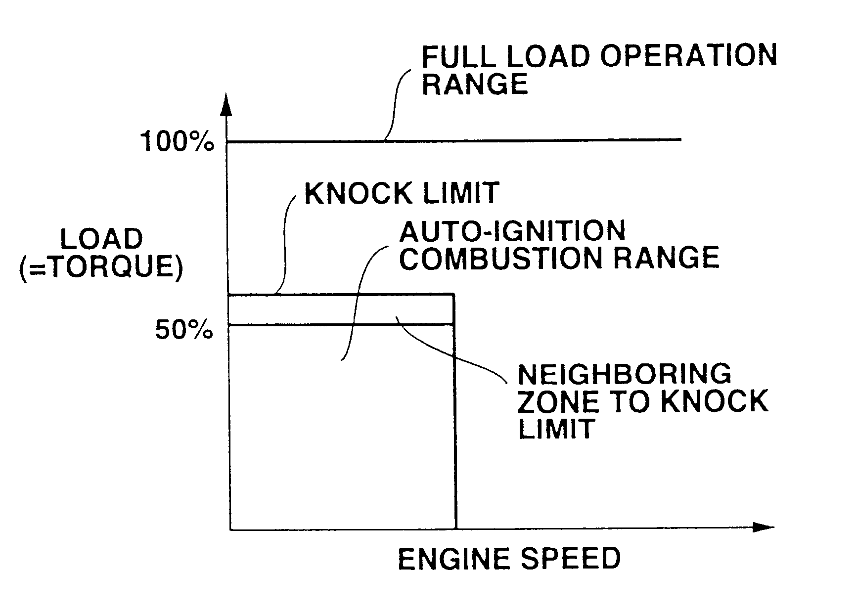
Under this combustion condition, increasing fuel quantity of the second injection may cause excessive pressure increase in cylinder and / or increased production of NOx.
If, as the ignition oil, ignitable fuel is used other than gasoline fuel, dual fuel delivery systems are needed, resulting in increased complexity.

Method used


Image

  • Auto-ignition combustion management in internal combustion engine
  • Auto-ignition combustion management in internal combustion engine
  • Auto-ignition combustion management in internal combustion engine

Examples


Embodiment Construction

Referring now to FIG. 3, a system for enhanced auto-ignition in a gasoline internal combustion engine is shown. The system, generally indicated by reference numeral 30, includes an engine 10 having a plurality of cylinders each fed by fuel injectors 18. The fuel injectors 18 are shown receiving pressurized gasoline fuel from a supply 32 which is connected to one or more high or low pressure pumps (not shown) as is well known in the art. Alternatively, embodiments of the present invention may employ a plurality of unit pumps (not shown), each pump supplying fuel to gasoline fuel to one of the injectors 18.

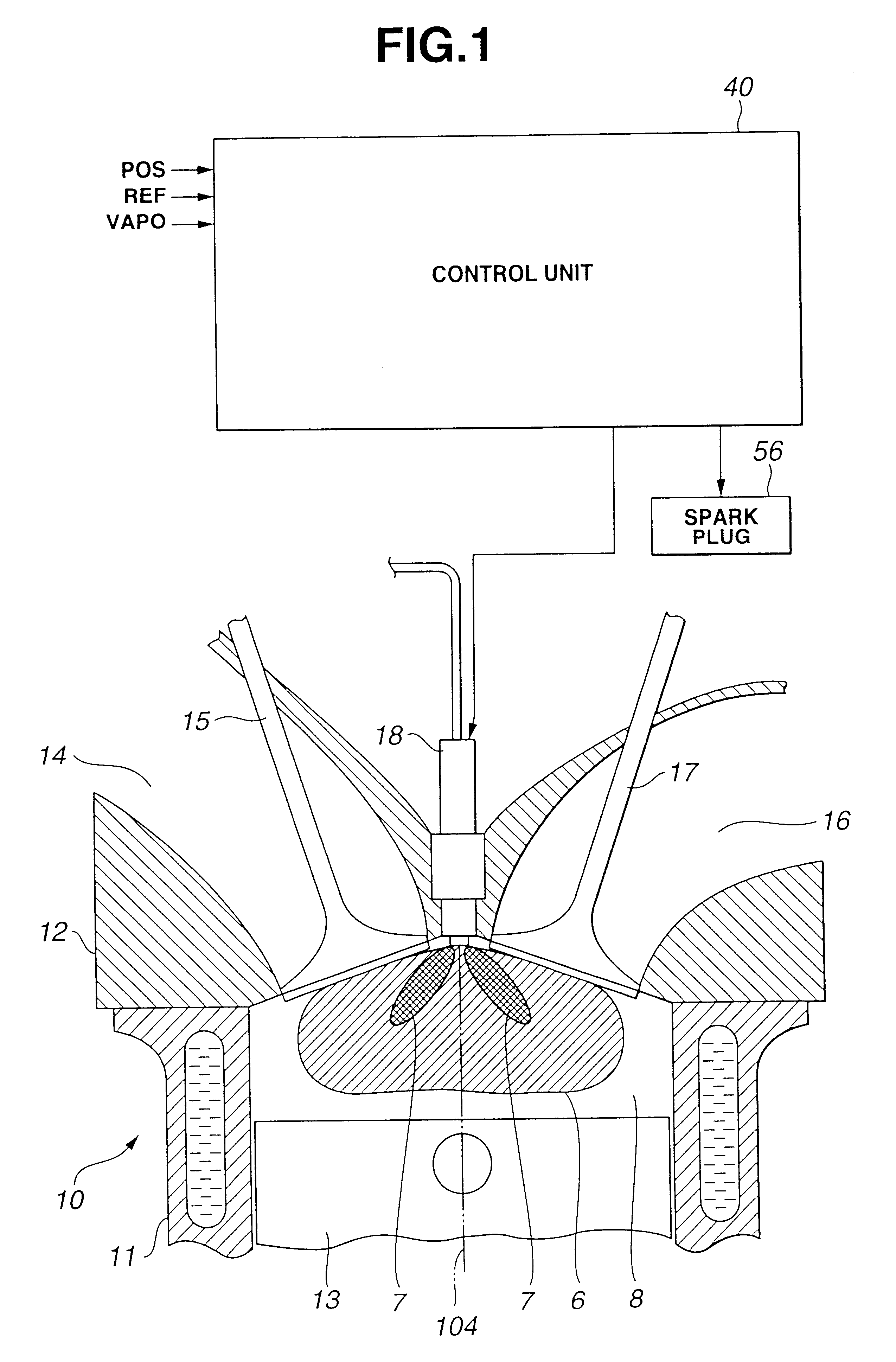
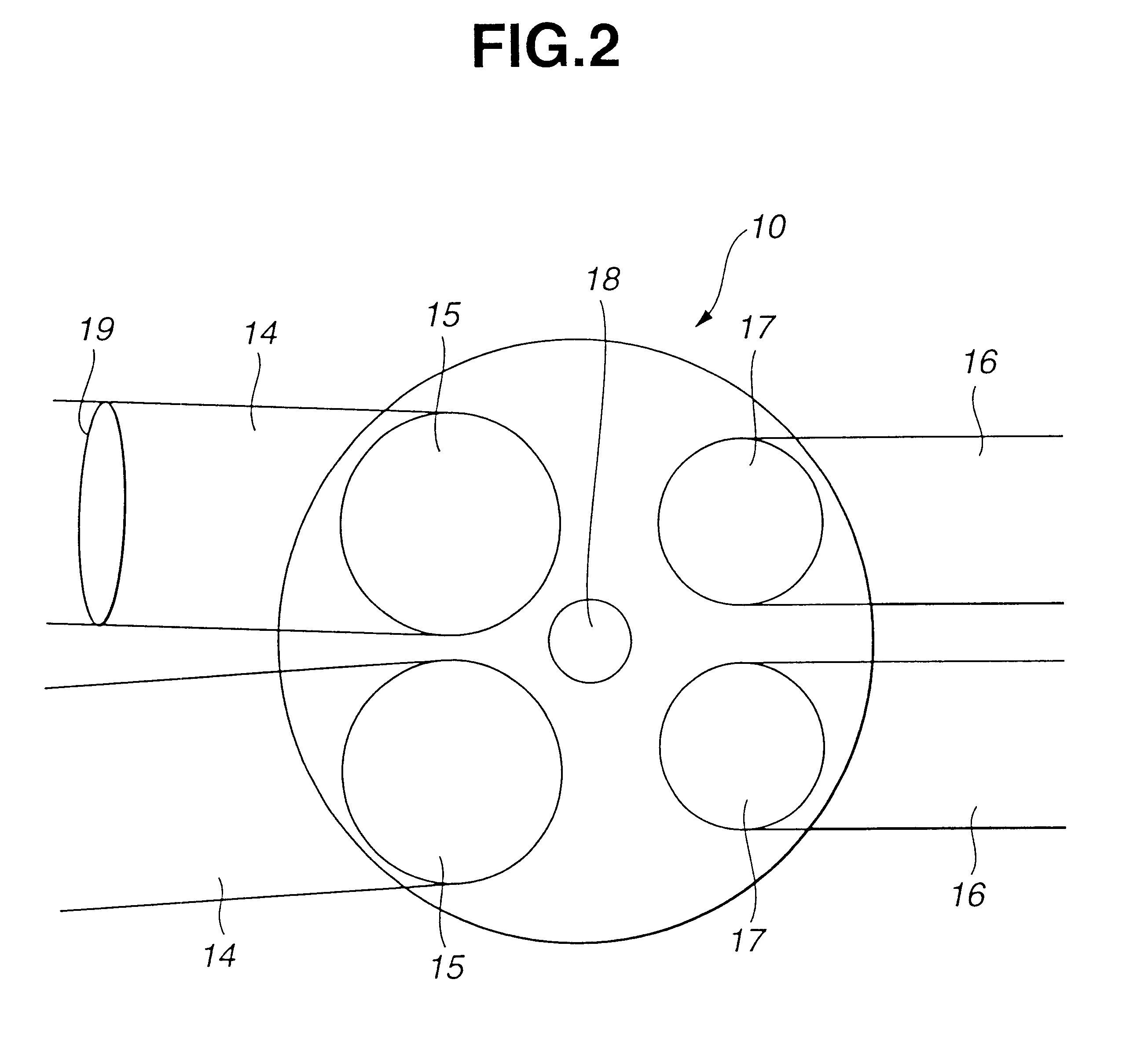
Referring also to FIGS. 1 and 2, in a preferred embodiment, engine 10 is a four-stroke cycle internal combustion engine capable of running under auto-ignition combustion of gasoline fuel and under spark-ignition combustion of gasoline fuel as well. The engine 10 includes a cylinder block 11 formed with a plurality of cylinders, only one being shown. A cylinder head 12 is attached to...


PUM


Abstract

An enhanced auto-ignition in a gasoline internal combustion engine, comprises a fuel injector directly communicating with said combustion chamber for spraying gasoline fuel. The fuel injector sprays a first injection quantity of gasoline fuel into a combustion chamber at first fuel injection timing, which falls in a range from the intake stroke to the first half of the compression stroke, thereby to form air / fuel mixture cloud that becomes a body of mixture as the engine piston moves from the first fuel injection timing toward a top dead center position of the compression stroke, and the fuel injector sprays a second injection quantity of gasoline fuel into the body of mixture at second fuel injection timing, which falls in the second half of the compression stroke, forming mixture cloud that is superimposed on a portion of said body of mixture, thereby to establish the cylinder content wherein the density of fuel particles within the superimposed portion is high enough to burn by auto-ignition at an ignition point in the neighborhood of the piston top dead center position of the compression stroke, causing temperature rise and pressure, which initiate auto-ignition of the fuel particles within the remaining portion of said body of mixture.

Description

1. Field of the InventionThe present invention relates to a system or method for enhanced auto-ignition in a gasoline internal combustion engine.2. Description of Related ArtTo improve thermal efficiency of gasoline internal combustion engines, lean burn is known to give enhanced thermal efficiency by reducing pumping losses and increasing ratio of specific heats. Flatly speaking, lean burn is known to give low fuel consumption and low NOx emissions. There is however a limit at which an engine can be operated with a lean air / fuel mixture because of misfire and combustion instability as a result of a slow burn. Known methods to extend the lean limit include improving ignitability of the mixture by enhancing the fuel preparation, for example using atomized fuel or vaporized fuel, and increasing the flame speed by introducing charge motion and turbulence in the air / fuel mixture. Finally, combustion by auto-ignition has been proposed for operating an engine with very lean air / fuel mixtu...

Claims


Application Information

Patent Timeline
Patent Type & Authority Patents(United States)
IPC IPC(8): F02B1/12F02D41/30F02B1/00F02B75/02
CPCF02B1/12F02D41/3047F02B2075/025
Inventor TERAJI, ATUSHINAITOH, KENYOSHIZAWA, KOUDAIAOCHI, EIJI
Owner NISSAN MOTOR CO LTD
Why Eureka
Try Eureka