Rack for loading parts for heat treatment

Inactive Publication Date: 2002-06-11
SN DETUDE & DE CONSTR DE MOTEURS DAVIATION S N E C M A
View PDF16 Cites 36 Cited by
  • Summary
  • Abstract
  • Description
  • Claims
  • Application Information

AI Technical Summary

Benefits of technology

Because it is made of thermostructural composite material and because it has horizontal arms with free ends, the rack provides the positioning and accessibility accuracy required for robotizing the operations of loading and unloading the parts to be treated. Thermostructural composite materials such as C/C and CMC composites are characterized by their dimensional stability and by their bending strength, thus making it possible to load the parts in a cantilevered-out position.
In addition, such a rack can be made to be lightweight and open-structured, while p

Problems solved by technology

the tooling is itself subjected to cementation and rapidly becomes brittle, which can give rise to a large amount of disorder in a furnace;
it must be bulky in order to avoid deforming excessively under load, since such deformation can in turn cause the supported parts to become deformed, requiring them to be rectified subsequently and consequently losing thickness in the cemented layer;
tooling that is bulky makes gas exchange more difficult and decreases loading efficiency, i.e. reduces the working fraction of the volume which it occupies by the parts to be treated;
violent thermal shock

Method used


Image

  • Rack for loading parts for heat treatment
  • Rack for loading parts for heat treatment
  • Rack for loading parts for heat treatment

Examples


Example

In the description below, reference is made to racks for metal parts for cementation. The invention is not limited to such an application and, more generally, covers carrying parts, whether made of metal or not, that are to be subjected to heat treatment.

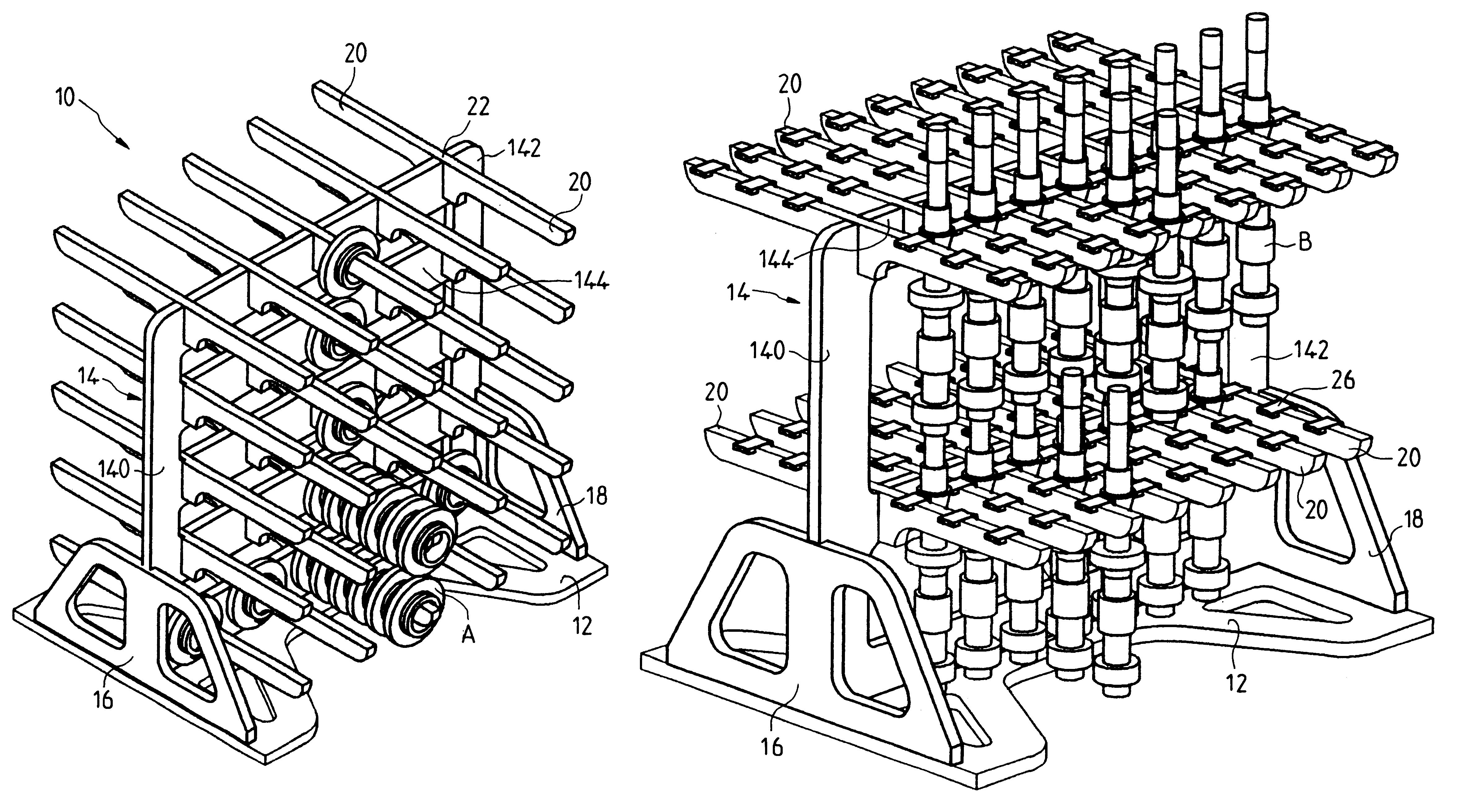
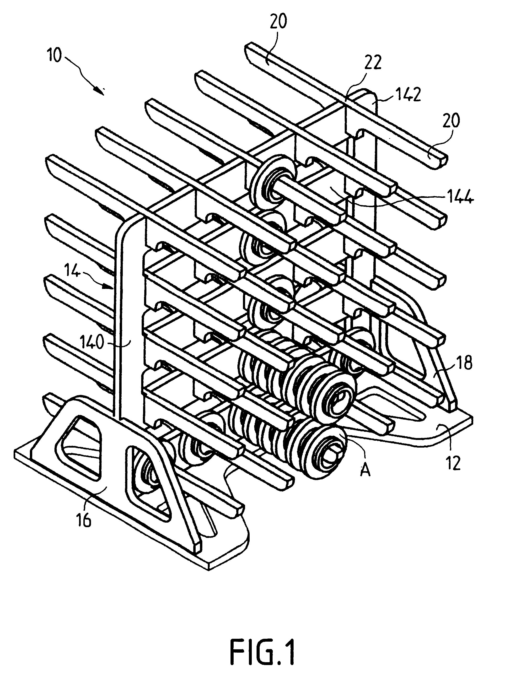
The rack 10 shown in FIG. 1 is intended specifically for supporting annular parts A such as gears for gear boxes. Only a few parts A are shown in FIG. 1.

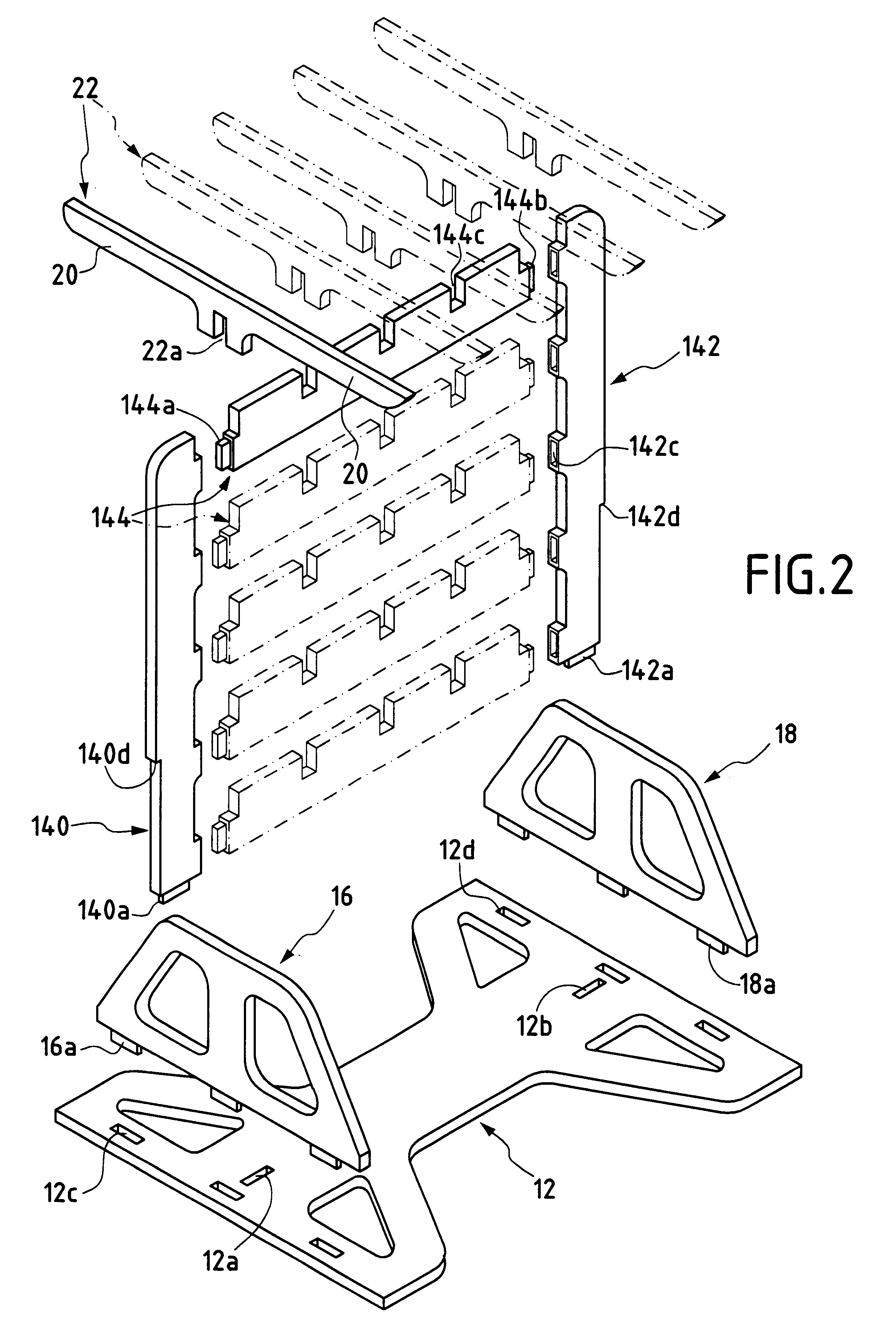
The rack comprises (FIGS. 1 and 2) a support structure essentially formed by a baseplate 12, a vertical partition 14 supported by the baseplate 12 in the middle thereof, lateral reinforcing gussets 16 and 18, and horizontal support arms 20. The central partition 14 comprises lateral uprights 140, 142 with horizontal cross-bars 144 extending between them. The support arms 20 are constituted by bars 22 whose central portions are supported by the cross-bars 144. The bars 22 extend on either side of the partition 14 so that each forms two arms in alignment and of the same dimensions. At...


PUM


Abstract

The rack is made essentially out of thermostructural composite material and comprises a baseplate (12), a partition (14) extending above the baseplate, and a plurality of support arms (20) fixed to the partition and extending substantially horizontally therefrom to their own free ends, so that parts to be treated (A) can be supported in cantilevered-out positions on said arms.

Description

The invention relates to a rack or tooling for supporting parts in a heat treatment furnace.A particular but non-exclusive field of application of the invention is that of tooling for supporting parts in a cementation furnace.In the above field, the tooling most commonly used is made of metal. It suffers from the following main drawbacks:the tooling is itself subjected to cementation and rapidly becomes brittle, which can give rise to a large amount of disorder in a furnace;it must be bulky in order to avoid deforming excessively under load, since such deformation can in turn cause the supported parts to become deformed, requiring them to be rectified subsequently and consequently losing thickness in the cemented layer;tooling that is bulky makes gas exchange more difficult and decreases loading efficiency, i.e. reduces the working fraction of the volume which it occupies by the parts to be treated;violent thermal shock can cause the metal to be deformed or to break; andthe inevitab...

Claims


Application Information

Patent Timeline
IPC IPC(8): F27D3/12F27D5/00C21D1/00C23C8/20
CPCF27D3/12F27D5/005F27D5/00A47F5/0815
Inventor MAUMUS, JEAN-PIERRE
Owner SN DETUDE & DE CONSTR DE MOTEURS DAVIATION S N E C M A
Why Eureka
Try Eureka