Band-changing repeater with protocol or format conversion

a repeater and protocol technology, applied in the field of repeaters, can solve the problems of extremely limited capacity of systems deployed previously in the united states, high cost of service, and inability to realize mobile telephony

Inactive Publication Date: 2002-06-11
ALLEN TELECOM LLC
View PDF3 Cites 508 Cited by
  • Summary
  • Abstract
  • Description
  • Claims
  • Application Information

AI Technical Summary

Benefits of technology

It is another object of the invention to provide a bidirectional repeater having a first terminal for communicating with components of a first communications system and a second terminal for communicating with components of a second communications system, thereby enabling communications between components of the first and second communications, wherein the components of the first and second communications systems are otherwise incompatible.
It is a further object of the invention to provide a bidirectional repeater having a terminal for communicating with components of a cellular communications system and a second terminal for communicating with components of PCS communications system, thereby enabling transparent communication between components of the cellular and PCS systems.

Problems solved by technology

Although the concept of mobile telephony was not new, the systems which had been deployed previously in the United States were extremely limited in capacity.
Prior to the advent of conventional cellular service, there were long waiting lists of persons desiring to subscribe to the existing systems, and service was very expensive.
System capacity was so limited that subscribers desiring to make a call sometimes had to wait tens of minutes for a radio channel to become available.
The positioning of PCS as a competitor to cellular systems presents special challenges to PCS system operators, particularly during the initial period of system deployment.
In many areas of the country it is not economically feasible to install PCS base stations and related infrastructure equipment due to the relatively lower population densities involved.
Since some PCS providers may compete directly with wireline cellular providers, it may be difficult and expensive to obtain carrier facilities from local telephone companies to connect base stations to switching offices.
Even in regions of relatively high population density, in many locations it may not be economically feasible to install PCS infrastructure equipment of conventional architecture during the early stages of PCS system implementation when subscriber demand is low.
However, this approach is only available if the "air protocol" to be used in the PCS system is identical (except for operating frequencies) to that implemented by the existing cellular base station equipment.
In general, if the air protocol of two systems are different, the systems are fundamentally incompatible, and terminals of one system cannot directly communicate with the terminals of the other system.
If the air protocols of the cellular base station equipment and the PCS system are not compatible, merely adding equipment to change the operating frequency of the cellular base station equipment will not allow that equipment to function as a base station in the PCS system.
Moreover, constructing a PCS base station using cellular base station components of existing design may be advantageous to an equipment manufacturer, but it does not resolve several problems faced by the PCS system operator (including those related to economic feasibility) in initially deploying a relatively large number of PCS base stations when subscriber density is low.
Since cellular base station equipment is generally designed for high density applications, use of modified cellular equipment in low-density PCS applications may have particularly onerous cost consequences to the PCS system operator.
These facilities are expensive to install and carry a high recurring charge.
The problem of providing initial PCS service, at a time or in a geographical region in which subscriber demand is low, and where a preexisting, highly developed cellular system is available, may be seen as a special case of a more general problem: that of allowing subscribers of a first communications system which employs a first radio interface to access a second communications system which employs a second radio interface which is incompatible because of differences between the two in an operating characteristic.
Several different trunked radio systems are commercially available, but because these systems employ different radio interfaces (or air protocols), equipment designed for different systems will not interoperate.

Method used


Image

  • Band-changing repeater with protocol or format conversion
  • Band-changing repeater with protocol or format conversion
  • Band-changing repeater with protocol or format conversion

Examples


Embodiment Construction

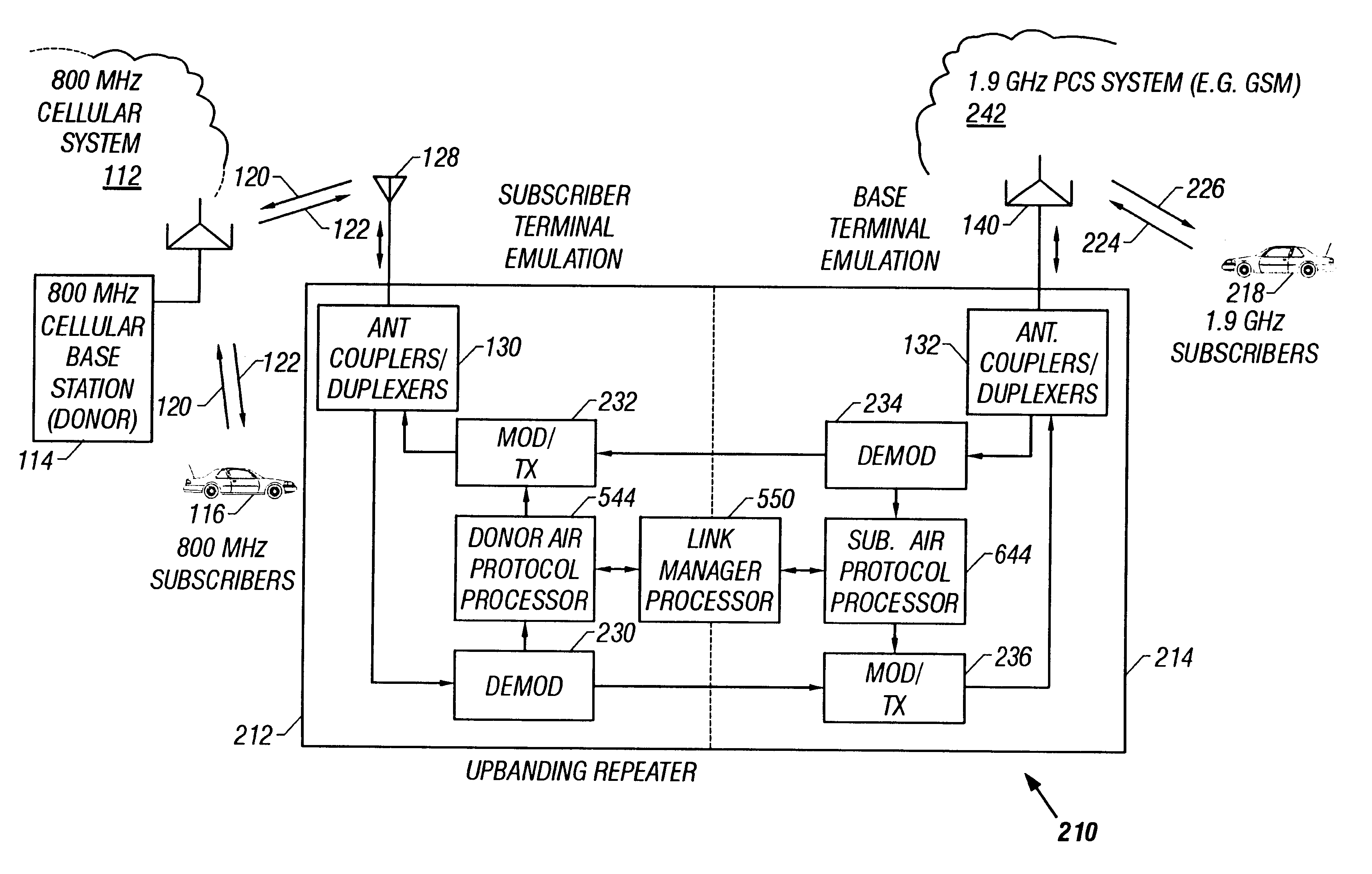
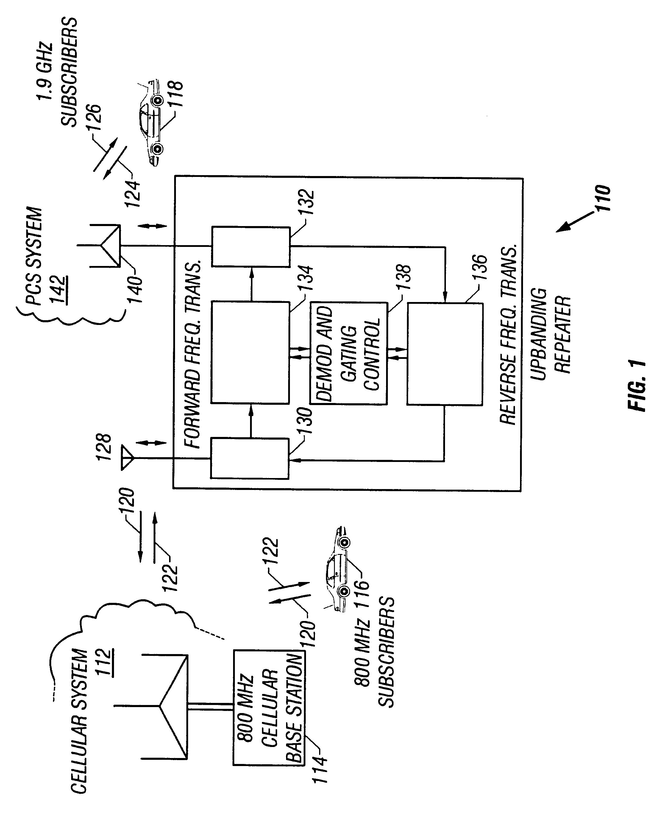
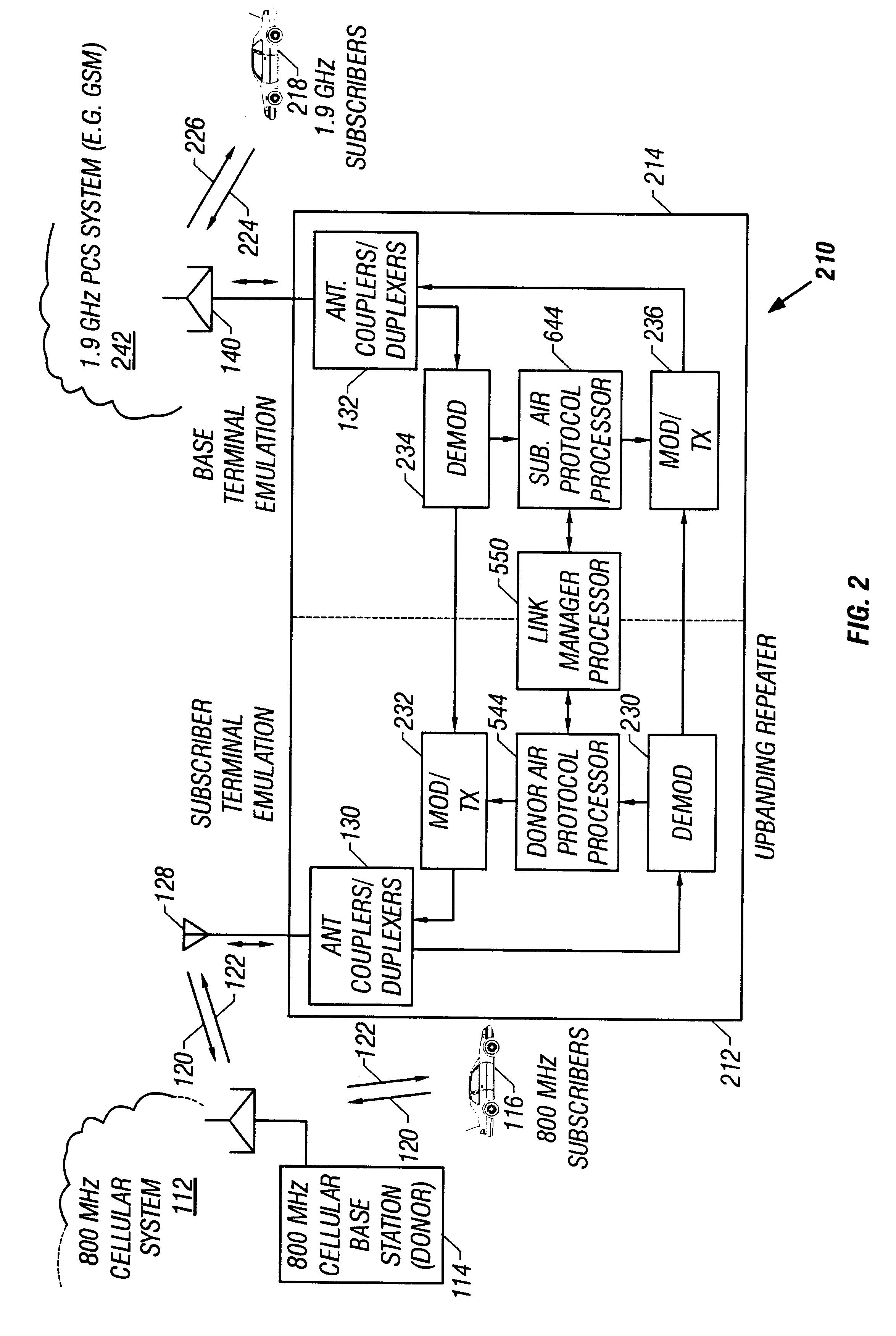
FIGS. 1-11 generally show preferred embodiments of a repeater constructed according to the present invention for allowing communications between terminals of first and second wireless communications systems, wherein the communications systems have non-identical air protocols or radio interfaces. Although the present invention is described in the exemplary environment of wireless communications systems typically used to provide mobile telephone service, the invention is broadly applicable to a wide variety of communications systems.

FIGS. 1 and 3-5 show a first preferred embodiment of a repeater constructed according to an aspect of the present invention, for use in applications in which the first and second communications systems operate in different frequency bands, but employ otherwise identical or compatible air protocols. FIGS. 2 and 6-11 show a second preferred embodiment of a repeater constructed according to another aspect of the present invention, for use in applications in w...


PUM


Abstract

A repeater allows terminals of a first communications system, employing a first air protocol or radio interface, to communicate with terminals of a second communications system, employing a second air protocol or radio interface different from the first. Where the first and second air protocols differ only in operating frequency, but are otherwise compatible, the repeater may linearly translate signals from the first operating frequency to the second operating frequency, and vice versa, without demodulating and remodulating the signals. Where the air protocols differ in other ways, the repeater receives and demodulates signals from the first system, converts the signals to a common format, and remodulates and retransmits the signals according to the second air protocol (and vice versa), in the same frequency bands or in different frequency bands. The repeater translates control and signalling information transmitted in compliance with one air protocol to a format which complies with the other air protocol and has the same or equivalent effect. For each of the two communications system, the repeater emulates the functions of a terminal in that communications system, so that corresponding terminals in that system may communicate transparently with the repeater. The repeater provides a connection between the two emulated terminals, thereby allowing a terminal of the first system to use the repeater to communicate with an otherwise incompatible terminal of the second system.

Description

FIELD OF THE INVENTIONThis application relates to wireless communications systems, and more particularly to repeaters for use in wireless telephone systems. Still more particularly, the application relates to repeaters for use with wireless telephone systems (or similar communications systems) having plural disparate radio interfaces differing in frequency band, format, or protocols, in which the repeater operates as a bridge to allow communication between components operating on such disparate interfaces.BACKGROUND OF THE INVENTIONIn 1983, conventional "analog" cellular telephone service became commercially available in several cities of the United States. This event marked the first time mobile telephone service was widely available to members of the general public. Although the concept of mobile telephony was not new, the systems which had been deployed previously in the United States were extremely limited in capacity. Prior to the advent of conventional cellular service, there ...

Claims


Application Information

Patent Timeline
Patent Type & Authority Patents(United States)
IPC IPC(8): H04B7/14H04B7/26H04Q7/30H04W88/08
CPCH04B7/15528H04W88/085H04B7/2606
Inventor LESLIE, SAMUEL A.GOINS, DONNIE L.BOWEN, WILLIAM A.
Owner ALLEN TELECOM LLC
Why Eureka
Try Eureka