Method in connection with personal non-invasive heartrate measuring arrangement with alarm
a heart rate monitor and alarm technology, applied in the field of heart rate monitors, can solve the problems of monotonous exercise, too steady exercise, and limited heart rate limit alarms, and achieve the effects of controlling the stress caused by exercise, easy and fast programming, and easy replacement or replacemen
- Summary
- Abstract
- Description
- Claims
- Application Information
AI Technical Summary
Benefits of technology
Problems solved by technology
Method used
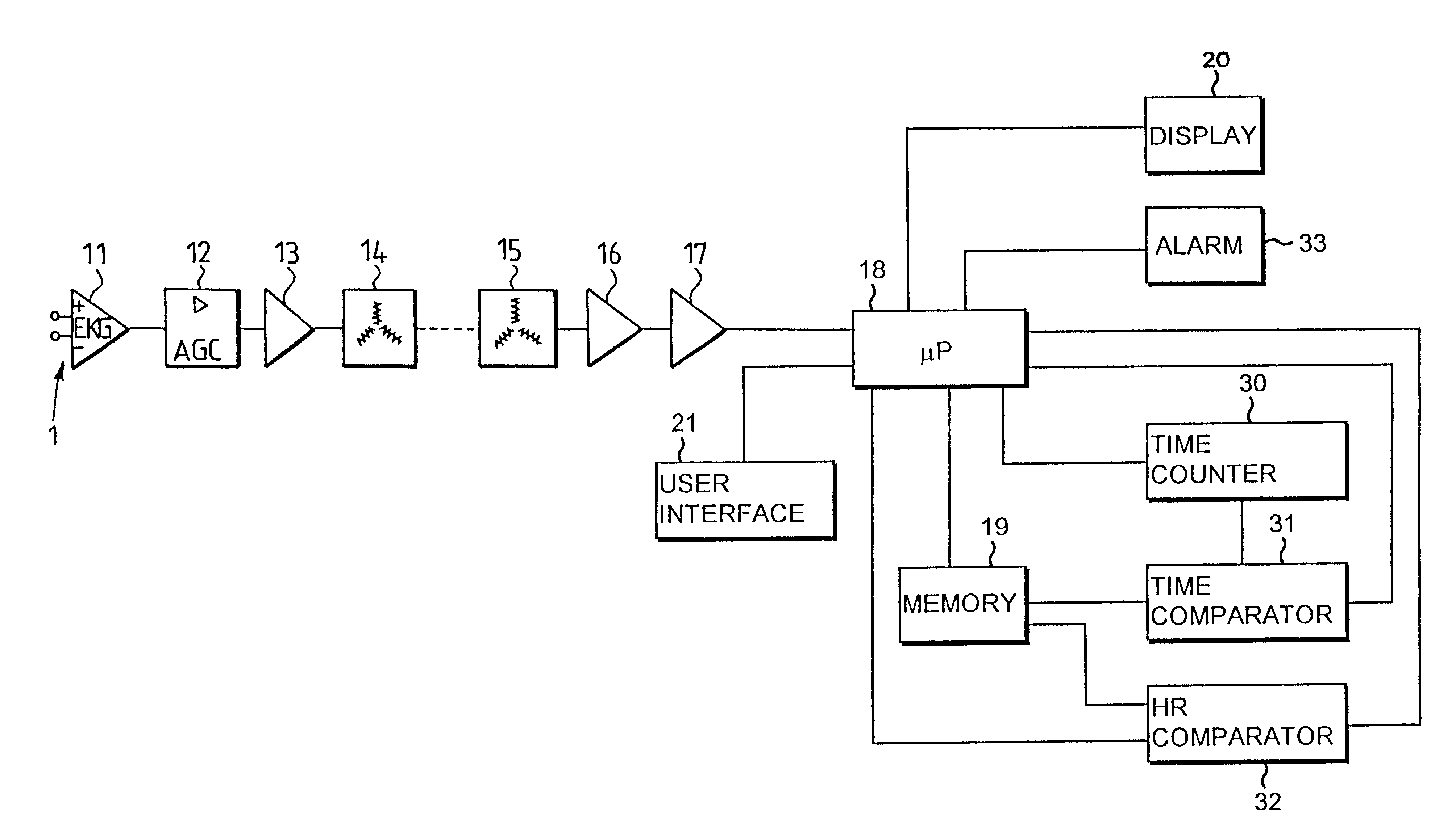
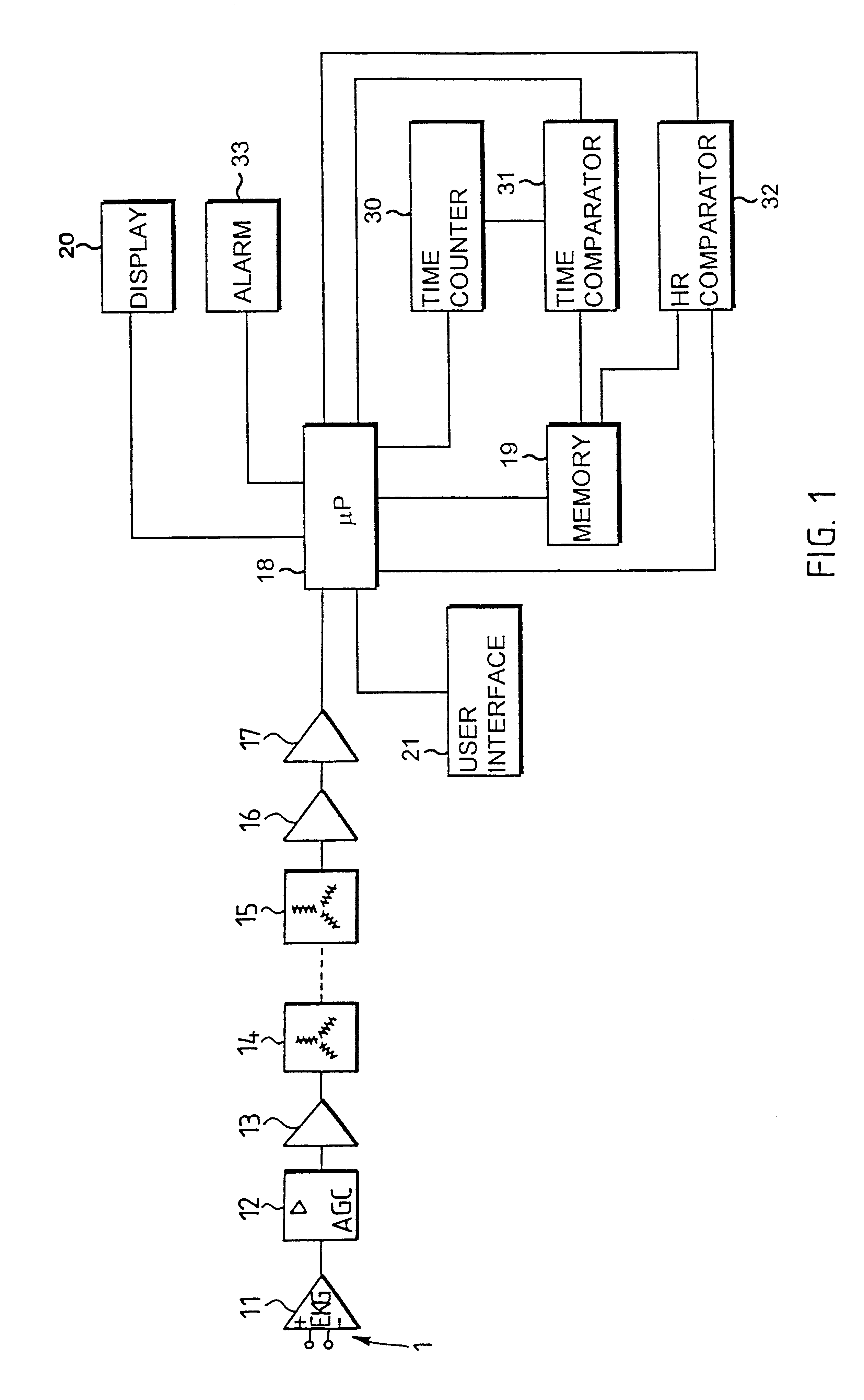
Image

Examples
first embodiment
The first embodiment illustrated in FIG. 5 shows an interval period where the section where the heart rate rises is between a lower heart rate limit pair LIM3 and the next higher heart rate limit pair LIM4 in the heart rate limit alarm sequence, and the section where the heart rate falls is between said higher heart rate limit pair LIM4 and the next lower heart rate limit pair LIM5.
second embodiment
The second embodiment illustrated in FIG. 6 shows an interval period where the section where the heart rate rises is between an individual low heart rate limit and the next higher heart rate limit pair in the heart rate limit alarm sequence, and the section where the heart rate falls is between said higher heart rate limit pair and the next individual lower heart rate limit.
third embodiment
the invention illustrated in FIG. 7 shows an interval period where the section where the heart rate rises is between the end point of the period of change and the next higher heart rate limit pair, and the section where the heart rate falls is the next period of change.
From the user's point of view, a good embodiment is one in which the information supplied in order to form heart rate limits and heart rate limit pairs is information directly indicating the heart rate limit values. For example, the user sets values 100 and 130 for the heart rate limit pairs to be used as the lower heart rate limit pairs, and values 150 and 180 for use as the higher heart rate limit pairs.
The same also applies to the supply of time information TIME1, TIME2, . . . and individual heart rate limits RECO HR and periods of change RECO TI, i.e. they are supplied directly as actual values, for example such that the recovery heart rate limit indicating the recovery of the user's heart rate in FIG. 6 is suppli...
PUM
 Abstract
Description
Claims
Application Information