
Stereolithographic method and apparatus for production of three dimensional objects using multiple beams of different diameters

a three-dimensional object and beam technology, applied in the field of stereolithographic methods and equipment for producing three-dimensional objects using multiple beams of different diameters, can solve the problems of large diameter light flux, failure to provide any teachings concerning the manipulation of object data to distinguish regions requiring small diameter light flux, and failure to teach the desirability of distinguishing cross-sectional regions from one another

Inactive Publication Date: 2002-06-18
3D SYST INC
View PDF45 Cites 83 Cited by
  • Summary
  • Abstract
  • Description
  • Claims
  • Application Information

AI Technical Summary

Benefits of technology

It is a second object of the present invention to provide three-dimensional objects with reduced object formation time.
It is a third object of the present invention to provide three-dimensional objects with enhanced resolution.

Problems solved by technology

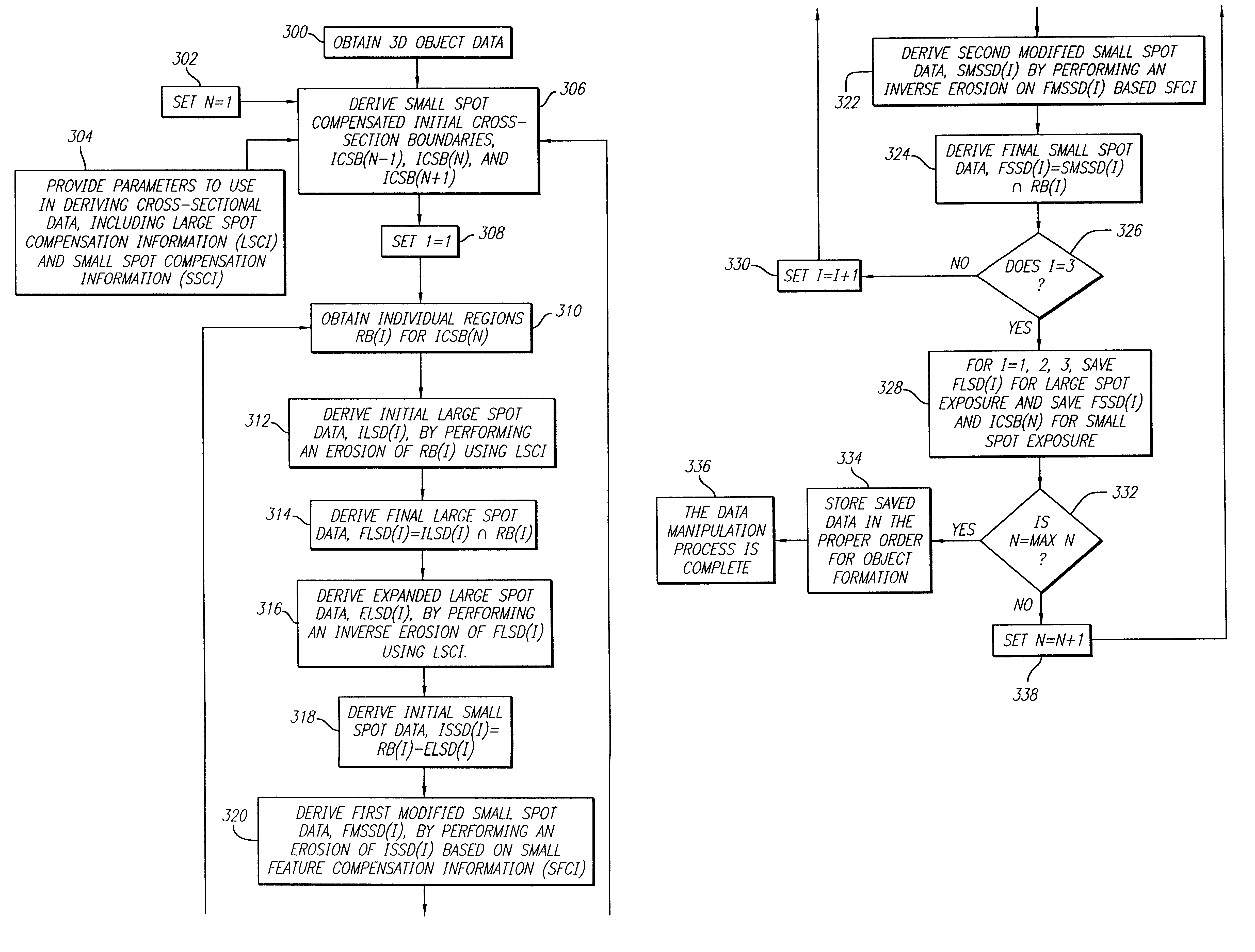
Though this patent teaches the desire to use a large diameter light flux and a small diameter light flux, it fails to provide any teachings concerning how to manipulate object data to distinguish regions requiring the small diameter light flux and those capable of being formed using the large diameter light flux.
This reference further fails to teach the desirability of distinguishing cross-sectional regions from one another when determining where to apply the large diameter and small diameter light fluxes.

Method used


Image

  • Stereolithographic method and apparatus for production of three dimensional objects using multiple beams of different diameters
  • Stereolithographic method and apparatus for production of three dimensional objects using multiple beams of different diameters
  • Stereolithographic method and apparatus for production of three dimensional objects using multiple beams of different diameters

Examples


Embodiment Construction

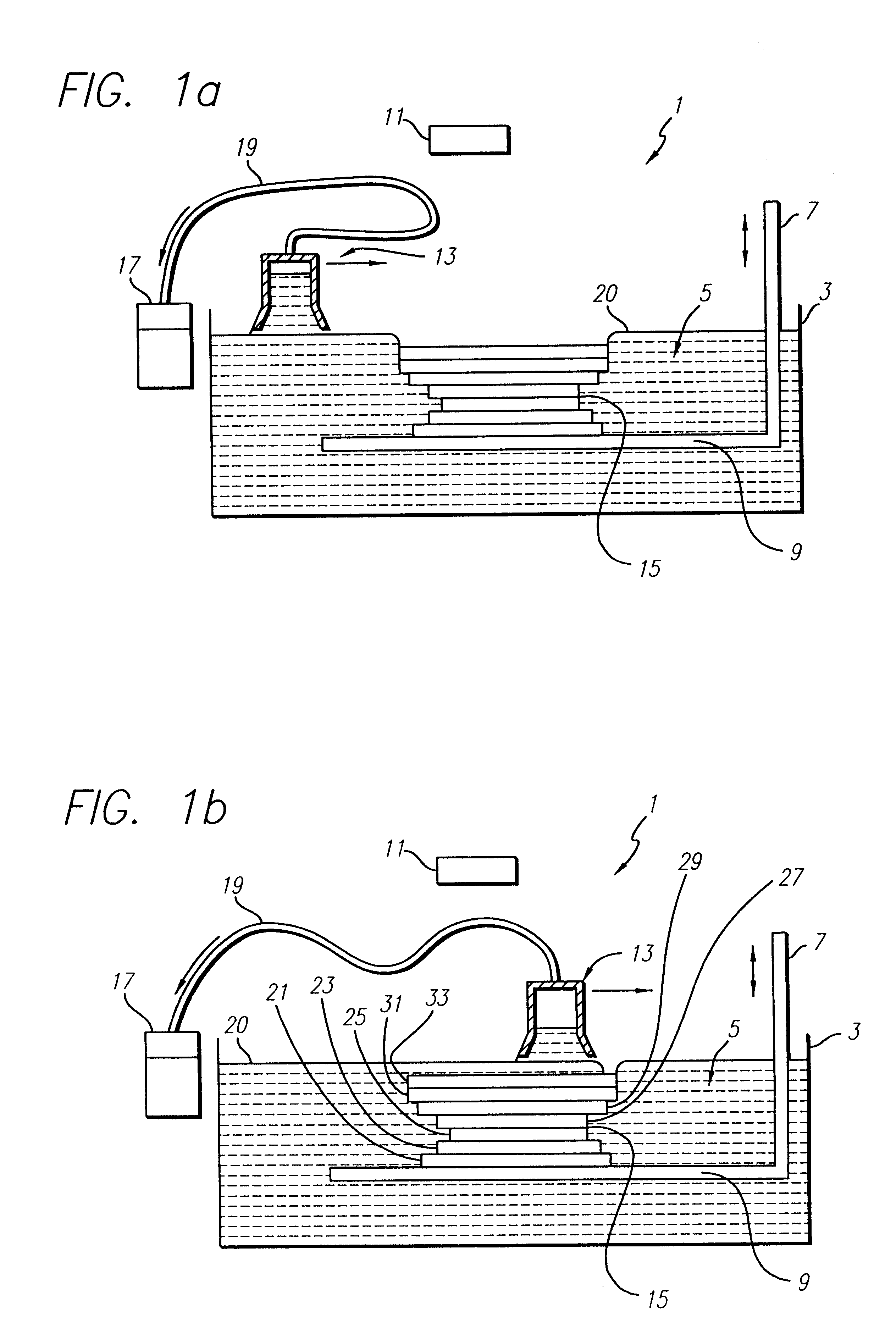
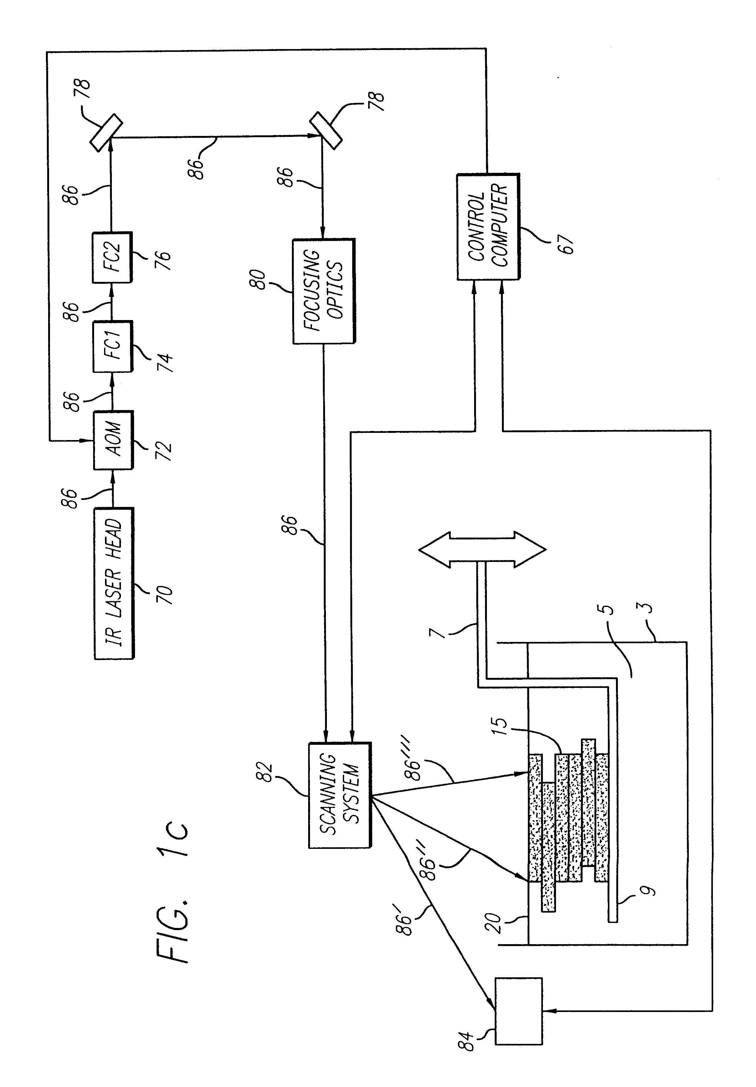
FIGS. 1a and 1b depict schematic representations of a preferred stereolithography apparatus 1 (SLA) for use with the instant invention. The basic components of an SLA.RTM. system are described in U.S. Pat. Nos. 4,575,330; 5,184,307; and 5,182,715 as referenced above. The preferred SLA.RTM. system includes container 3 for holding building material 5 (e.g. photopolymer) from which object 15 will be formed, elevator 7 and driving means (not shown), elevator platform 9, exposure system 11, recoating bar 13 and driving means (not shown), at least one computer (not shown) for manipulating object data (as needed) and for controlling the exposure system, elevator, and recoating device.

FIG. 1a depicts the partially formed object as having its most recently formed lamina lowered to a position approximately one layer thickness below the desired level of the upper surface of the building material 5 (i.e. desired working surface). As the layer thickness is small and the building material very vi...


PUM

PropertyMeasurementUnit
Poweraaaaaaaaaa
Diameteraaaaaaaaaa
Areaaaaaaaaaaa

Abstract

A rapid prototyping and manufacturing (e.g. stereolithography) method and apparatus for making three-dimensional objects on a layer by layer basis by selectively exposing layers of material to prescribed stimulation, using a beam having a first smaller diameter and a beam having a second larger diameter, to form laminae of the object. The power of the smaller beam is typically lower than the power of the larger beam. Object formation is controlled by data representing portions of the layers to be exposed with the larger beam (large spot portions) and those portions to be exposed with the smaller beam (small spot portions). In a preferred embodiment, portions exposed with the larger beam are formed first, for a given layer. Portions are exposed with the small beam next. Thereafter the entire perimeter of the laminae is traced using the small beam. Data manipulation techniques are used to identify which portions may be formed with the large beam to decrease exposure time and which should be formed with the small beam to maintain accuracy of the lamina being formed. More than two beam diameters may be used.

Description

This invention relates to the formation of three-dimensional objects using a Rapid Prototyping and Manufacturing (RP&M) technique. The invention more particularly relates to the stereolithographic formation of three-dimensional objects using a plurality of different dimensioned beams of radiation.1. Related ArtRapid Prototyping and Manufacturing (RP&M) is the name given to a field of technologies that can be used to form three-dimensional objects rapidly and automatically from three-dimensional computer data representing the objects. RP&M can be considered to include three classes of technologies: (1) Stereolithography, (2) Selective Deposition Modeling, and (3) Laminated Object Manufacturing.The stereolithography class of technologies creates three-dimensional objects based on the successive formation of layers of a fluid-like material adjacent to previously formed layers of material and the selective solidification of those layers according to cross-sectional data representing suc...

Claims


Application Information

Patent Timeline
IPC IPC(8): B29C67/00
CPCB29C67/0092B29K2995/0073B33Y10/00B33Y30/00B29C64/40
Inventor MANNERS, CHRIS R.GUERTIN, MICHELLE D.NGUYEN, HOP D.PARTANEN, JOUNI P.TANG, NANSHENGEVERETT, MICHAEL A.
Owner 3D SYST INC
Learn More