Device and method for separating components of a fluid sample

a technology for fluid samples and components, applied in separation processes, liquid displacement, laboratory glassware, etc., can solve the problems of clogging the measuring instruments, and affecting the accuracy of the measuremen

Inactive Publication Date: 2002-06-18
BECTON DICKINSON & CO
View PDF32 Cites 204 Cited by
  • Summary
  • Abstract
  • Description
  • Claims
  • Application Information

AI Technical Summary

Benefits of technology

Another notable advantage of the present invention is that fluid specimens are not subjected to low density gel residuals that are at times available in products that use gel.
A further attribute of the present invention is that there is no interference with instrument probes.
Another attribute of the present invention is that samples for blood banking tests are more acceptable than when a gel separator is used.
Another attribute of the present invention is that only the substantially cell-free serum fraction of a blood sample is exposed to the top surface of the separator, thus providing practitioners with a clean sample.
Additionally, the assembly of the present invention does not require any additional steps or treatment by a medical practitioner, whereby a blood or fluid sample is drawn in the standard fashion, using standard sampling equipment.

Problems solved by technology

Moreover, the shelf-life of the product is limited in that over time globules may be released from the gel mass.
These globules have a specific gravity that is less than the separated serum and may float in the serum and may clog the measuring instruments, such as the instrument probes used during the clinical examination of the sample collected in the tube.
Such clogging can lead to considerable downtime for the instrument to remove the clog.
No commercially available gel is completely chemically inert to all analytes.
If certain drugs are present in the blood sample when it is taken, there can be an adverse chemical interaction with the gel interface.

Method used


Image

  • Device and method for separating components of a fluid sample
  • Device and method for separating components of a fluid sample
  • Device and method for separating components of a fluid sample

Examples


Embodiment Construction

The present invention may be embodied in other specific forms and is not limited to any specific embodiments described in detail, which are merely exemplary. Various other modifications will be apparent to and readily made by those skilled in the art without departing from the scope and spirit of the invention. The scope of the invention will be measured by the appended claims and their equivalents.

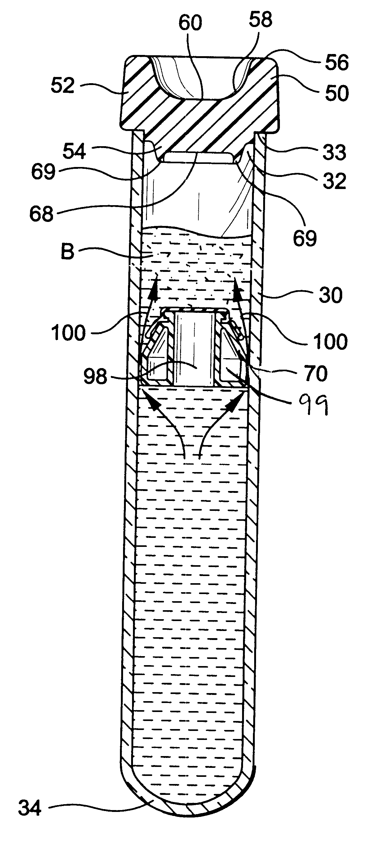
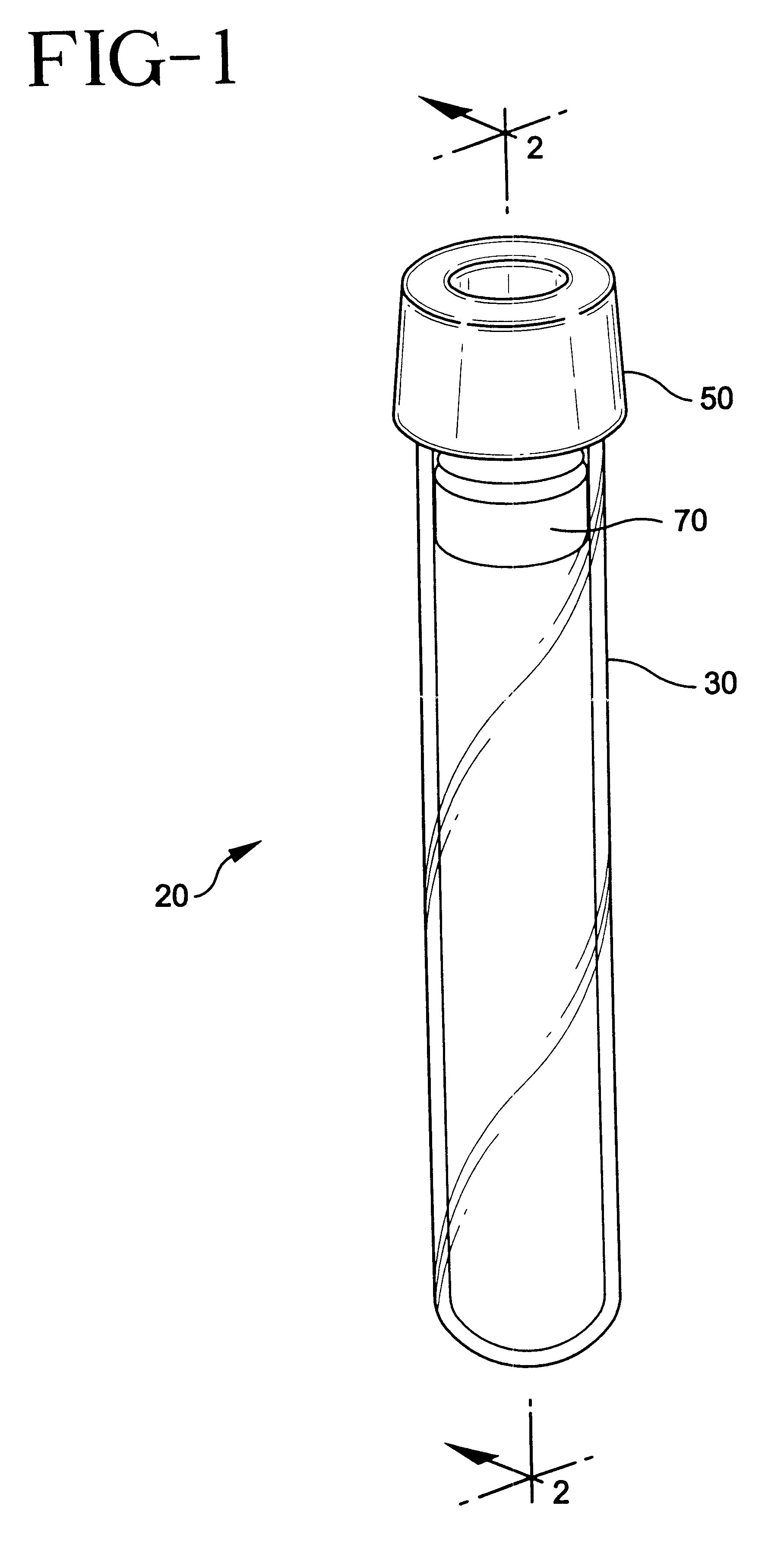
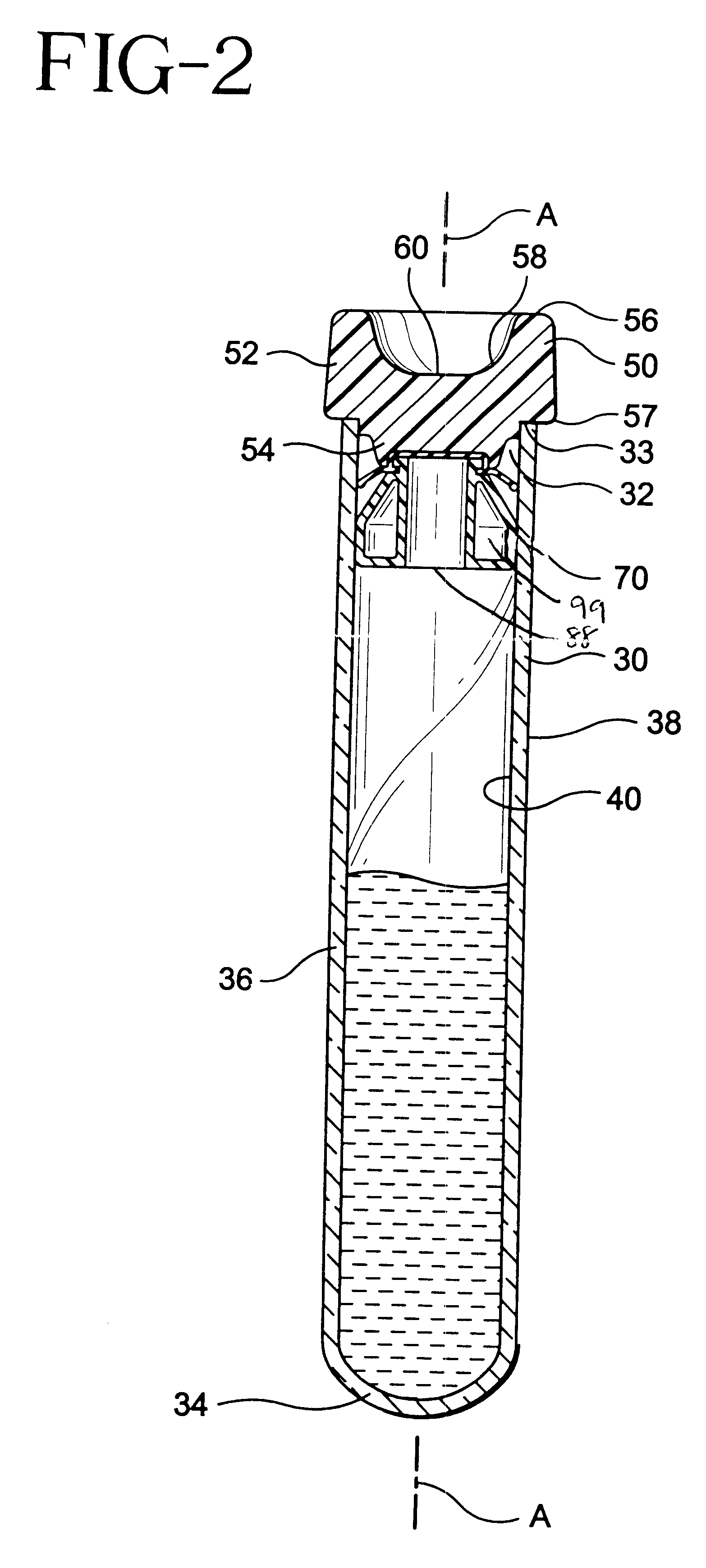
The preferred apparatus of the present invention is illustrated in FIGS. 1 to 5, wherein assembly 20 comprises a tube 30, a closure 50 and a separator 70.

Tube 30 has an open end 32 that includes a top edge 33, a closed end 34 and a sidewall 36 extending between the open end and the closed end. Sidewall 36 has an outer surface 38 and an inner surface 40. Tube 30 defines a receptacle with a central axis "A".

Tube 30 is preferably made from a substantially transparent and rigid material. Suitable materials for the tube include glass, polystyrene, polyethyleneterephthalate, polycarbonate and t...


PUM

PropertyMeasurementUnit
specific gravityaaaaaaaaaa
densityaaaaaaaaaa
specific gravityaaaaaaaaaa

Abstract

A device and method is provided for separating heavier and lighter fractions of a fluid sample. The device includes a plurality of constituents comprising a container and a composite element in the container. The composite element is a separator comprising at least two components and more particularly an elastic portion and a plug member. A fluid sample is delivered to the container and the device is subjected to centrifugation whereby the centrifugal load causes the elastic portion of the separator to deform so that the separator migrates into the fluid sample and stabilizes between the heavier and lighter fractions of the fluid sample. The elastic portion of the separator will resiliently return to its initial configuration upon termination of the centrifugal load such that the elastic portion sealingly engages the container and separates the heavier and lighter fractions of the fluid sample.

Description

BACKGROUND OF THE INVENTION1. Field of the InventionThis invention relates to a device and method for separating heavier and lighter fractions of a fluid sample. More particularly, this invention relates to a device and method for collecting and transporting fluid samples whereby the device and fluid sample are subjected to centrifugation to cause separation of the heavier fraction from the lighter fraction of the fluid sample.2. Description of Related ArtDiagnostic tests may require separation of a patient's whole blood sample into components, such as serum or plasma, the lighter phase component, and red blood cells, the heavier phase component. Samples of whole blood are typically collected by venipuncture through a cannula or needle attached to a syringe or an evacuated collection tube. Separation of the blood into serum or plasma and red blood cells is then accomplished by rotation of the syringe or tube in a centrifuge. Such arrangements use a barrier for moving into an area ad...

Claims


Application Information

Patent Timeline
Patent Type & Authority Patents(United States)
IPC IPC(8): B01L3/14G01N33/49B01L99/00
CPCB01L3/50215G01N33/491B01L2400/0633Y10T436/255Y10T436/25375Y10T436/2575
Inventor DICESARE, PAUL C.COHEN, RICHMOND
Owner BECTON DICKINSON & CO
Why Eureka
Try Eureka