Variable hysteresis circuit

Inactive Publication Date: 2002-06-18
WABASH NATIONAL
View PDF6 Cites 8 Cited by
  • Summary
  • Abstract
  • Description
  • Claims
  • Application Information

AI Technical Summary

Benefits of technology

Another object of an embodiment of the present invention is to provide information to an ECM which will result in more efficient and effective braki

Problems solved by technology

As the wheel speed becomes very slow, the signal becomes generally unreliable.
Typically, designers of ABS's assume that when the wheel speed is less than 2 mph, the signal, received from each wheel sensor is unreliable.
However, certain factors create imperfections in the signal.
These imperfections can result in the ECM 14 incorrectly calculating the wheel speed.
One factor which adversely affects the sinusoidal signal produced by the VR sensor is mechanically induced noise.
Because sensors, such as VR sensors, are generally prone to mechanically induced noise, the sensor will produce significant AC voltage even though the wheel is stationary.
This situation is further complicated by the fact that the mechanical noise tends to be at a relatively high frequency.
Thus the high frequency noise causes a great rate of change of flux.
Because a VR sensor, for example, responds to the rate of change of flux, the resulting signal will

Method used


Image

  • Variable hysteresis circuit
  • Variable hysteresis circuit
  • Variable hysteresis circuit

Examples


Embodiment Construction

While the invention may be susceptible to embodiment in different forms, there is shown in the drawings, and herein will be described in detail, a specific embodiment with the understanding that the present disclosure is to be considered an exemplification of the principles of the invention, and is not intended to limit the invention to that as illustrated and described herein.

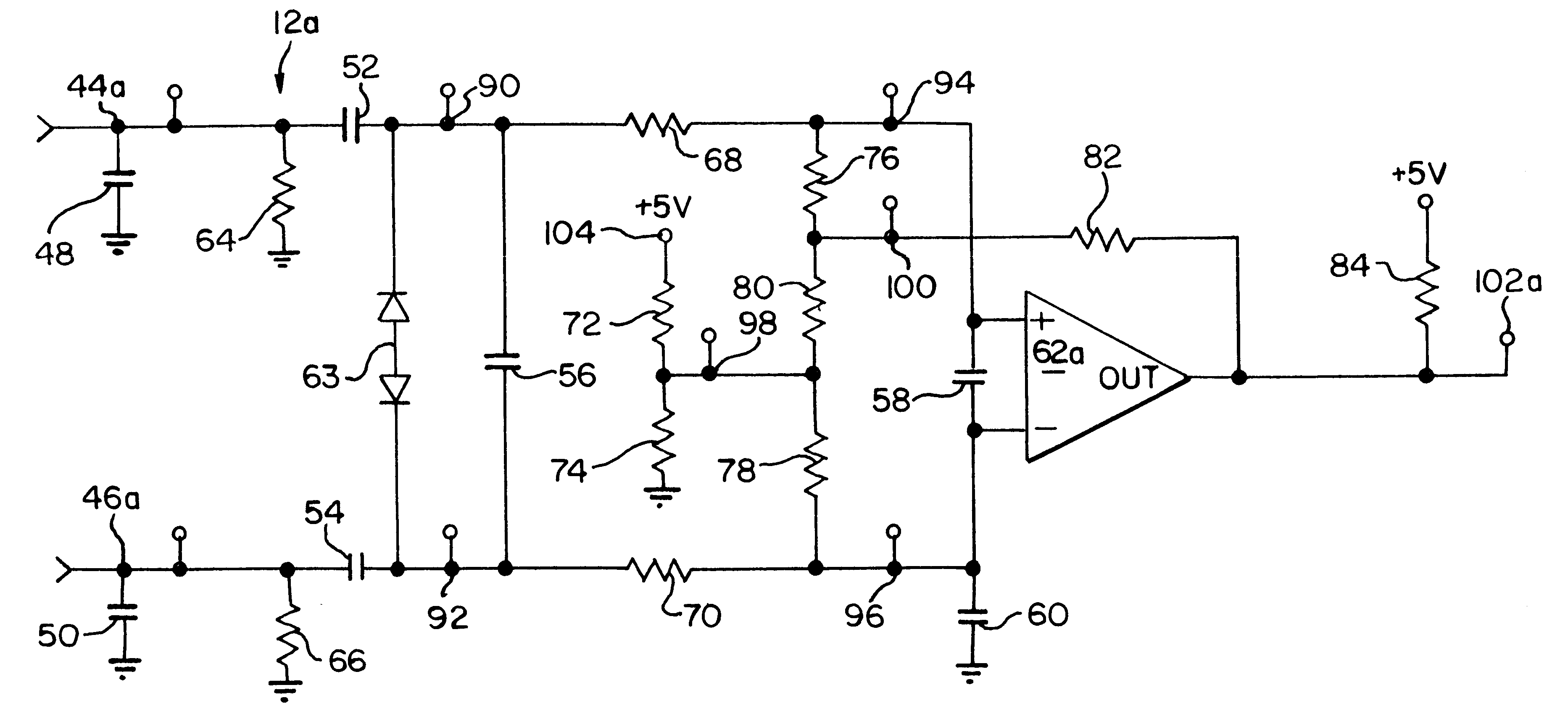
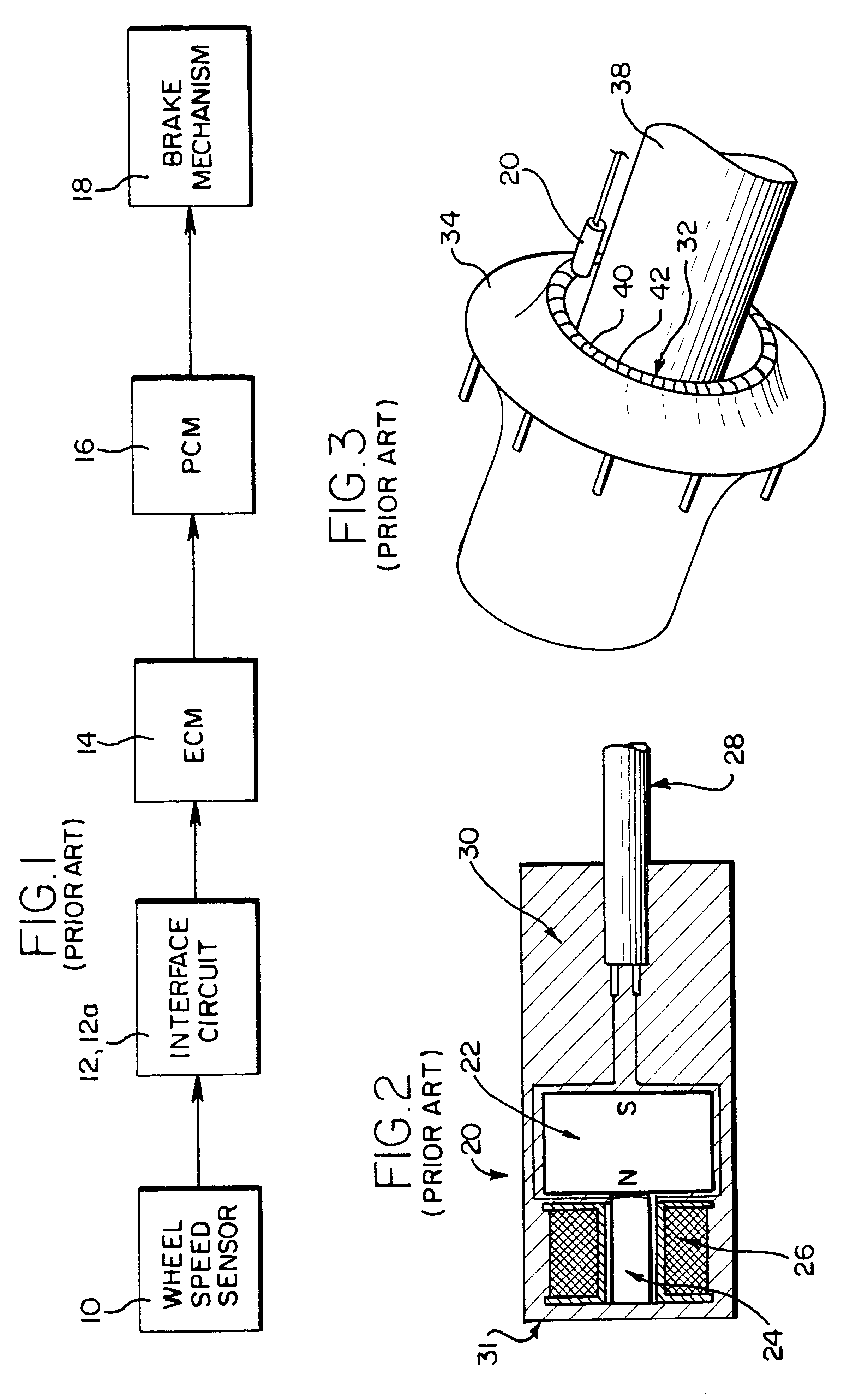
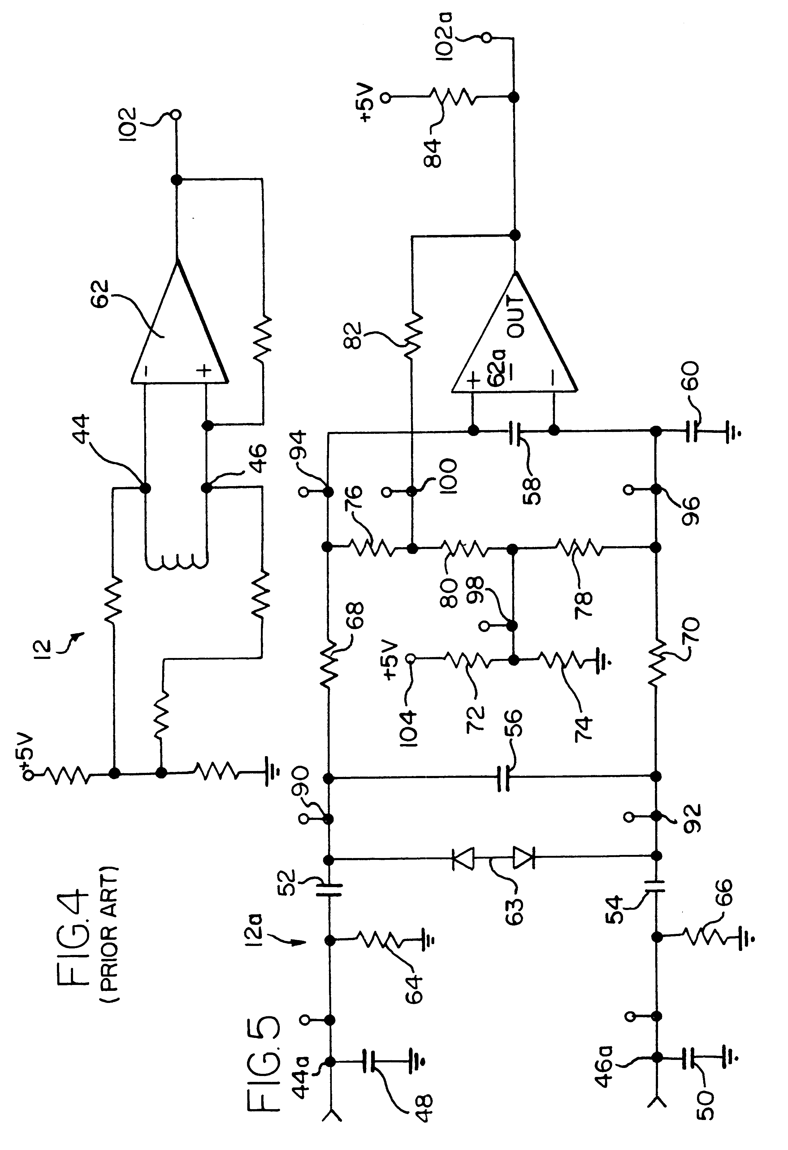
As shown in FIG. 5 and as will be described in detail hereinbelow, an embodiment of the present invention provides a circuit 12a which is configured to apply variable hysteresis to an input signal. As such, the circuit 12a provides improved noise rejection and other advantages. It is advantageous to employ such a circuit in connection with an ABS as shown schematically in FIG. 1. Specifically the circuit 12a can be used as the interface circuit between each wheel sensor 10 and the ECM 14.

One advantage of the interface circuit 12a shown in FIG. 5 is that when the road wheels are rotating slowly, a signal which ...


PUM


Abstract

The present invention provides a circuit which is configured to apply variable hysteresis to an input signal, where the level of hysteresis applied to the input signal is dependent upon the frequency of the input signal. Use of this circuit in a vehicle's anti-lock braking system allows for more efficient and effective braking.

Description

The present invention relates generally to circuits which provide a hysteresis function, and more specifically relates to circuits used in anti-lock braking systems(ABS).ABS used in conjunction with air-braked truck trailers are in common use. An objective of an ABS is to allow the wheels of a vehicle to continue to rotate during braking, including heavy braking. Keeping the wheels moving during braking generally provides more efficient braking. As shown in FIG. 1, an ABS generally consists of wheel speed sensors 10, an Interface circuit 12, an Electronic Control Module(ECM) circuit 12, an Electronic Control Module(ECM) 14, a Pneumatic Control Module (PCM) 16, and brake mechanisms 18 associated with the wheels of the vehicle. The ECM 14 is sometimes referred to as the Electronic Control Unit (ECU). The PCM 16 is sometimes referred to as the modulator and, in some anti-lock braking systems, the PCM is integrated into another component such as a relay valve.An ABS for air brakes gener...

Claims


Application Information

Patent Timeline
IPC IPC(8): H03K3/0233H03K3/00
CPCH03K3/02337
Inventor MCCANN, GERARD O.
Owner WABASH NATIONAL
Why Eureka
Try Eureka