Battery construction having double seam cover closure

Inactive Publication Date: 2002-06-25
ENERGIZER BRANDS
View PDF28 Cites 32 Cited by
  • Summary
  • Abstract
  • Description
  • Claims
  • Application Information

AI Technical Summary

Problems solved by technology

Consequently, a reduction in the amount of the electrochemical materials that may be provided within the cell results in a shorter service life for the cell.
However, such collector assemblies

Method used


Image

  • Battery construction having double seam cover closure
  • Battery construction having double seam cover closure
  • Battery construction having double seam cover closure

Examples


first embodiment

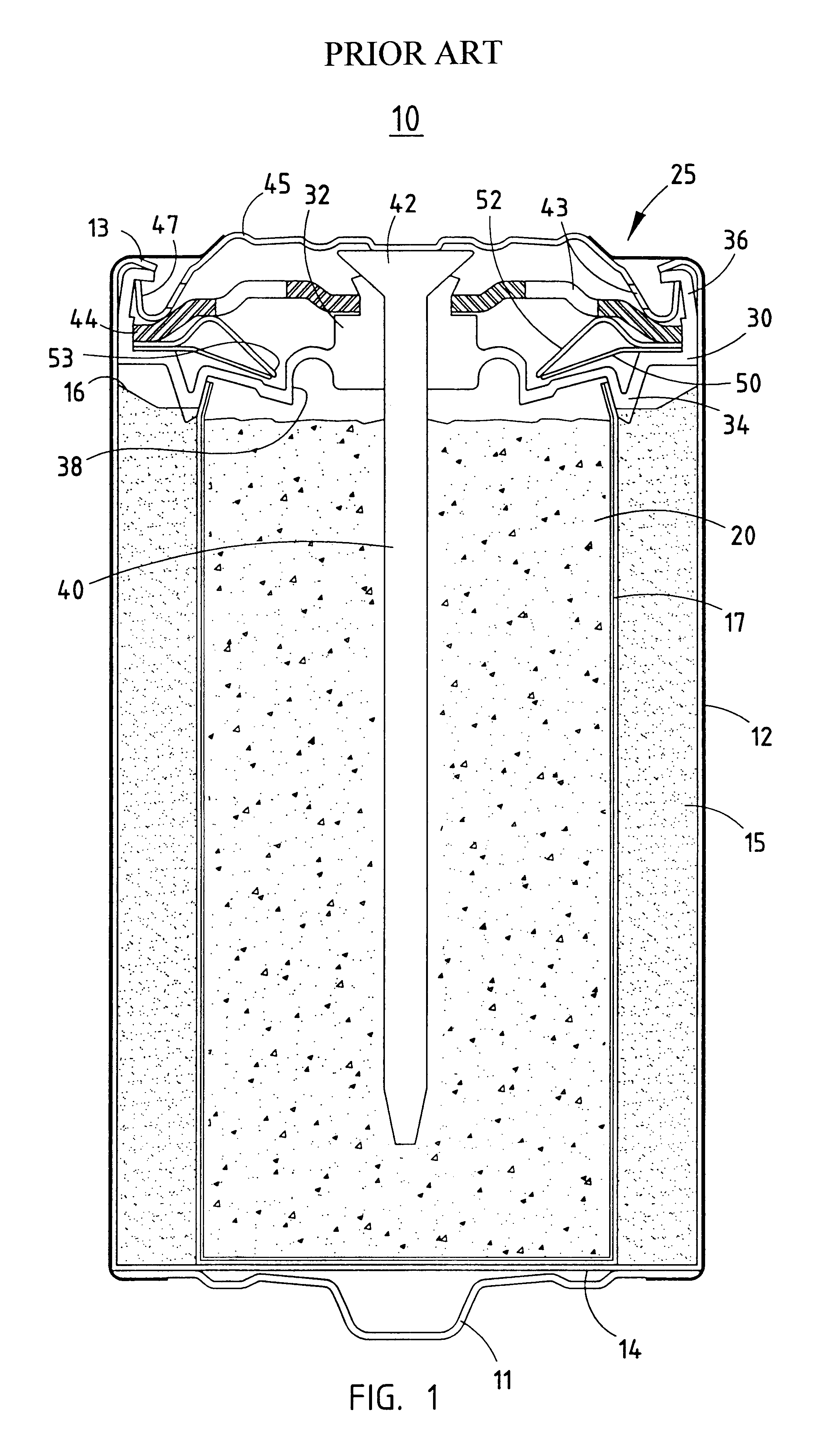
FIG. 4 shows a battery constructed using a low profile seal in accordance with the present invention. Similar to the battery shown in FIG. 1, battery 100 includes an electrically conductive can 112 having a closed end 114 and an open end in which a collector assembly 125 and negative cover 145 are secured in place. Also, battery 100 includes a positive electrode 115 in contact with the interior walls of can 112 and in contact with a separator layer 117 that lies between positive electrode 115 and a negative electrode 120. Further, battery 100 includes a positive outer cover 111 attached to a bottom surface of the closed end of can 112 and a label 160 applied over the side walls of can 112.

The difference between batteries 10 and 100 lies in the construction of collector assembly 125 and cover 145. While seal 130 is similar to seal 30 in that it includes an upstanding wall 136 and a central hub 132, which has an aperture formed therein for receiving the head portion 142 of a collector...

second embodiment

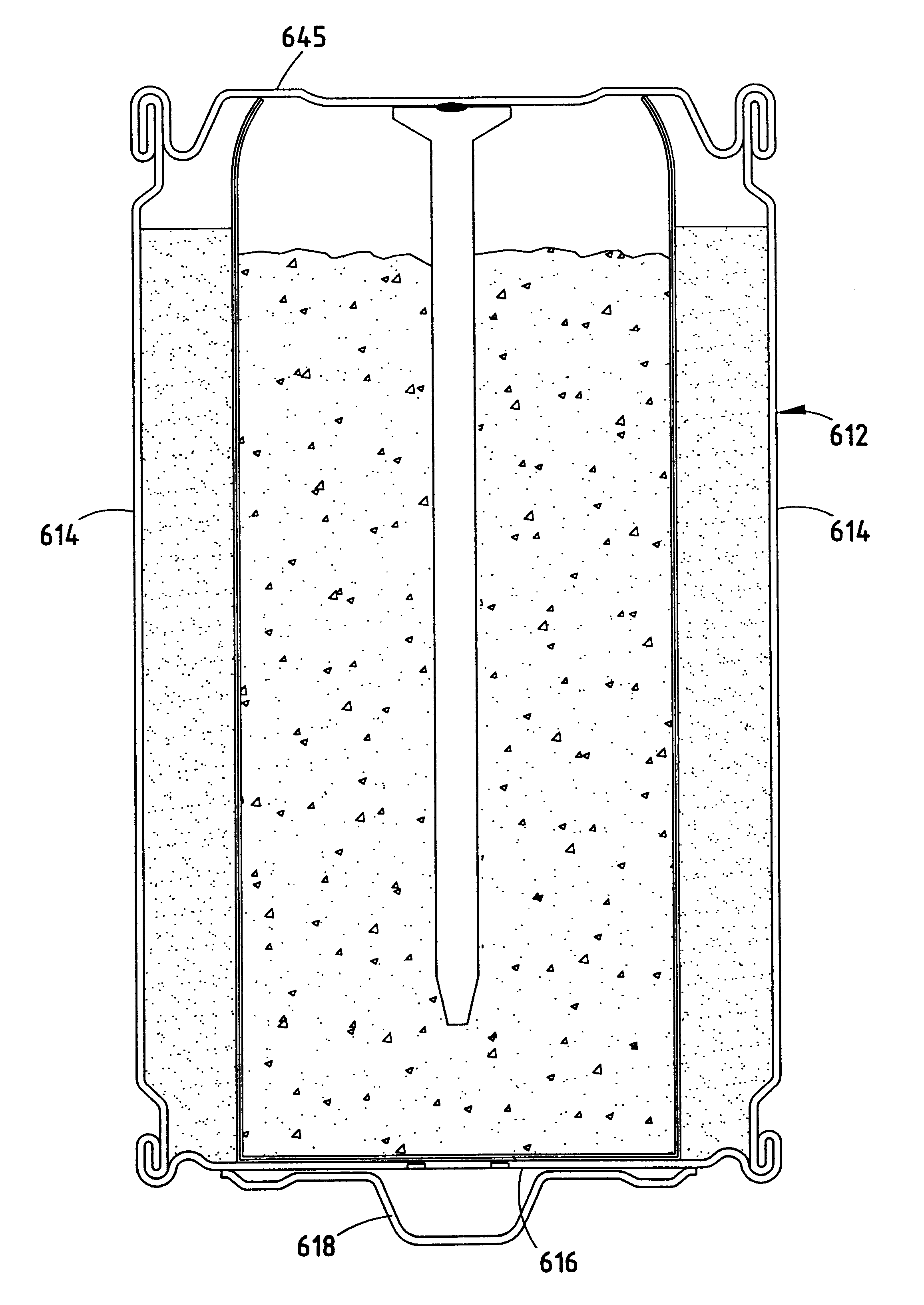
FIG. 6 shows a battery constructed in accordance with the present invention, which utilizes an ultra low profile seal. Like the conventional cell 10 shown in FIG. 1, cell 200 also includes a cylindrical can 212 made of an electrically conductive material. Also, a first electrode 215 is formed against the inner walls of can 212 preferably by molding. A separator 217 is likewise inserted within the cavity defined by first electrode material 215, and a mixture 220 of a second electrode and electrolyte are provided within a cavity defined by the separator 217.

As shown in FIG. 6, collector assembly 225 includes an integral seam / inner cover assembly 228 and a collector 240 that passes through a central hole 236 provided in the integral seal / inner cover assembly 228. Collector 240 is preferably a brass nail including a head 242 and a retainer flange 241 that is provided to cooperate with a speed nut 250 to secure collector nail 240 within central hole 236 of integrated seal / inner cover ass...

fourth embodiment

An electrochemical battery 300 constructed in accordance with the present invention is shown in FIGS. 8A through 8C. Battery 300 differs from the prior battery constructions in that a pressure relief mechanism 370 is formed in the closed end 314 of can 312. As a result, complex collector / seal assemblies may be replaced with collector assemblies that consume less volume and have fewer parts. Thus, a significant improvement in internal cell volume efficiency may be obtained. As shown in FIGS. 8A, 8B, 9, and 10, the pressure relief mechanism 370 is formed by providing a groove 372 in the bottom surface of can 312. This groove may be formed by coining a bottom surface of can 312, cutting a groove in the bottom surface, or molding the groove in the bottom surface of the can at the time the positive electrode is molded. For an AA sized battery, the thickness of the metal at the bottom of the coined groove is approximately 2 mils. For a D sized battery, the thickness of the metal at the bo...


PUM


Abstract

An electrochemical cell constructed in accordance with the present invention includes a can for containing electrochemical materials including positive and negative electrodes and an electrolyte, the can having an open end and a closed end; a pressure relief mechanism formed in the closed end of the can for releasing internal pressure from within the can when the internal pressure becomes excessive; a first outer cover positioned on the closed end of the can to be in electrical contact therewith and to extend over the pressure relief mechanism; a second outer cover positioned across the open end of the can; and an insulator disposed between the can and the second outer cover for electrically insulating the can from the second outer cover. According to another embodiment, the second cover is dielectrically isolated from a current collector. The second cover is fastened to the can by the use of a double-seamed closure.

Description

BACKGROUND OP THE INVENTIONThe present invention generally relates to an electrochemical cell construction. More particularly, the present invention relates to the containers and collector assemblies used for an electrochemical cell, such as an alkaline cell.FIG. 1 shows the construction of a conventional C sized alkaline cell 10. As shown, cell 10 includes a cylindrically-shaped can 12 having an open end and a closed end. Can 12 is preferably formed of an electrically conductive material, such that an outer cover 11 welded to a bottom surface 14 at the closed end of can 12 serves as an electrical contact terminal for the cell.Cell 10 further typically includes a first electrode material 15, which may serve as the positive electrode (also known as a cathode). The first electrode material 15 may be preformed and inserted into can 12, or may be molded in place so as to contact the inner surfaces of the can 12. For an alkaline cell, first electrode material 15 will typically include Mn...

Claims


Application Information

Patent Timeline
IPC IPC(8): H01M2/32H01M4/70H01M6/04H01M2/02H01M2/08H01M4/75H01M2/20H01M2/12H01M6/08H01M2/04H01M6/06H01M50/119H01M50/121H01M50/128H01M50/133H01M50/167H01M50/171H01M50/186H01M50/193H01M50/571
CPCH01M2/023H01M6/08H01M2/0267H01M2/0272H01M2/0275H01M2/0408H01M2/0413H01M2/0417H01M2/0421H01M2/08H01M2/12H01M2/1241H01M2/32H01M4/75H01M2/0235H01M4/70H01M6/06H01M50/56H01M50/182H01M50/1243H01M50/154H01M50/171H01M50/30H01M50/3425H01M50/571H01M50/133H01M50/121H01M50/186H01M50/193H01M50/119H01M50/128H01M50/167
Inventor TUCHOLSKI, GARY R.SONDECKER, GEORGE R.
Owner ENERGIZER BRANDS
Why Eureka
Try Eureka