Slotted induction heater

a heating device and induction heating technology, applied in the field of induction heating devices, can solve the problems of high cost, bulky and inefficient water cooling systems, and increased temperature of coils and surrounding structures,

Inactive Publication Date: 2002-07-02
AUTO KAPS +1
View PDF46 Cites 28 Cited by
  • Summary
  • Abstract
  • Description
  • Claims
  • Application Information

AI Technical Summary

Benefits of technology

Consequently, there is very little room for error in providing current having a proper frequency to the tuned LCR circuit. Indeed, as the frequency of the delivered current moves away from resonance, the gain of the LCR circuit is greatly reduced and the current falls below that which is necessary to properly heat the foil liner 22. It is noted that the prior art sealing heads also have Q factors; however, such Q factors of the prior art are much lower than that of the preferred embodiment of the present invention.
Advantageously, the litz wire coil 128 has a very low resistance to the flow of current therein as compared to conventional copper tubing used in prior art devices. More specifically, since high frequency currents tend to flow near the surface of wire (known as the "skin effect") the use of multi-strand litz wire in the coil 128 reduces the resistance of the coil 128 to current flow. Litz wire having about 4,000 strands of individually insulated conductors have been available commercially. However, it is most preferred that litz wire having 10,000 insulated strands therein be used in the litz wire core 128. Such 10,000 strand litz wire has been specially manufactured for use in the present invention.
Thus, in accordance with the preferred embodiment of the present invention, the litz wire coil 128 is sized such that the effective resistance per unit length is only about 0.1-0.01 that of the copper tubing of the prior art. Consequently, the heat produced within the litz wire coil 128 (due to I.sup.2 R losses) is reduced by a factor of 10-100 and water cooling of the sealing head 120 is not required. Indeed, the coil heat sink 122 provides all the heat dissipation necessary to safely and efficiently operate the induction sealing unit 100.

Problems solved by technology

In conventional systems, high currents are produced in the coil of the sealing head and, due to the relatively high resistance of the coil, results in the drastic elevation of the temperature of the coil and any surrounding structures.
Unfortunately, the water cooling systems which cool the sealing heads (via hollow copper tubing coils) are expensive, bulky and inefficient.

Method used


Image

  • Slotted induction heater
  • Slotted induction heater
  • Slotted induction heater

Examples


Embodiment Construction

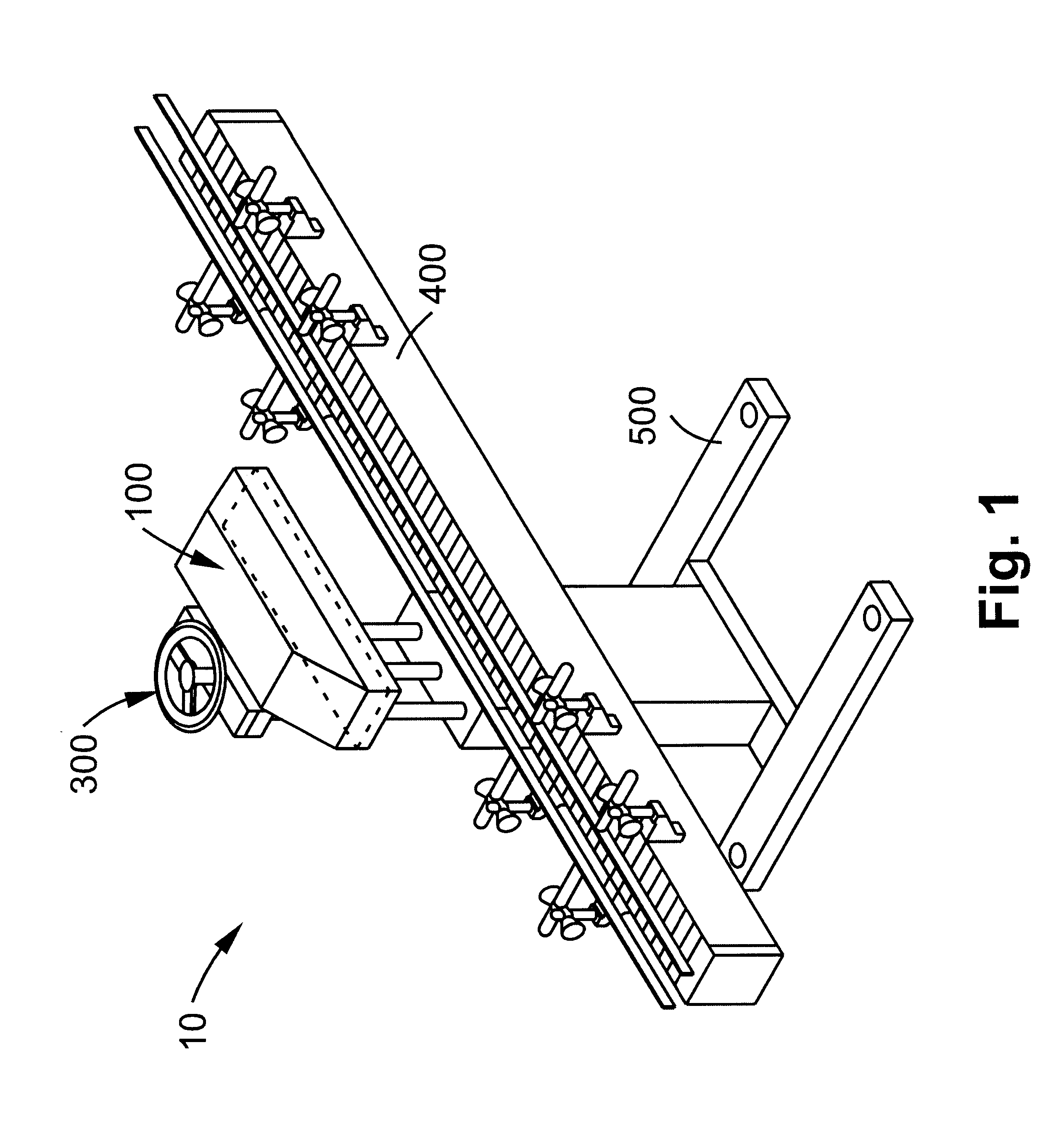
With reference to FIG. 1, the induction sealing conveyor system 10 includes an induction sealing unit 100, an adjustment mechanism 300, a conveyor 400, and a base 500. The adjustment mechanism 300 adjustably couples the induction sealing unit 100 to the base 500. Thus, the induction sealing unit 100 may be raised or lowered with respect to the base 500 and the conveyor 400 for insuring that the induction sealing unit is the proper distance from a container to be sealed which travels down the conveyor 400. The adjustment mechanism 300 and the conveyor 400 are well-known in the art and, therefore, a detailed description relating thereto is omitted.

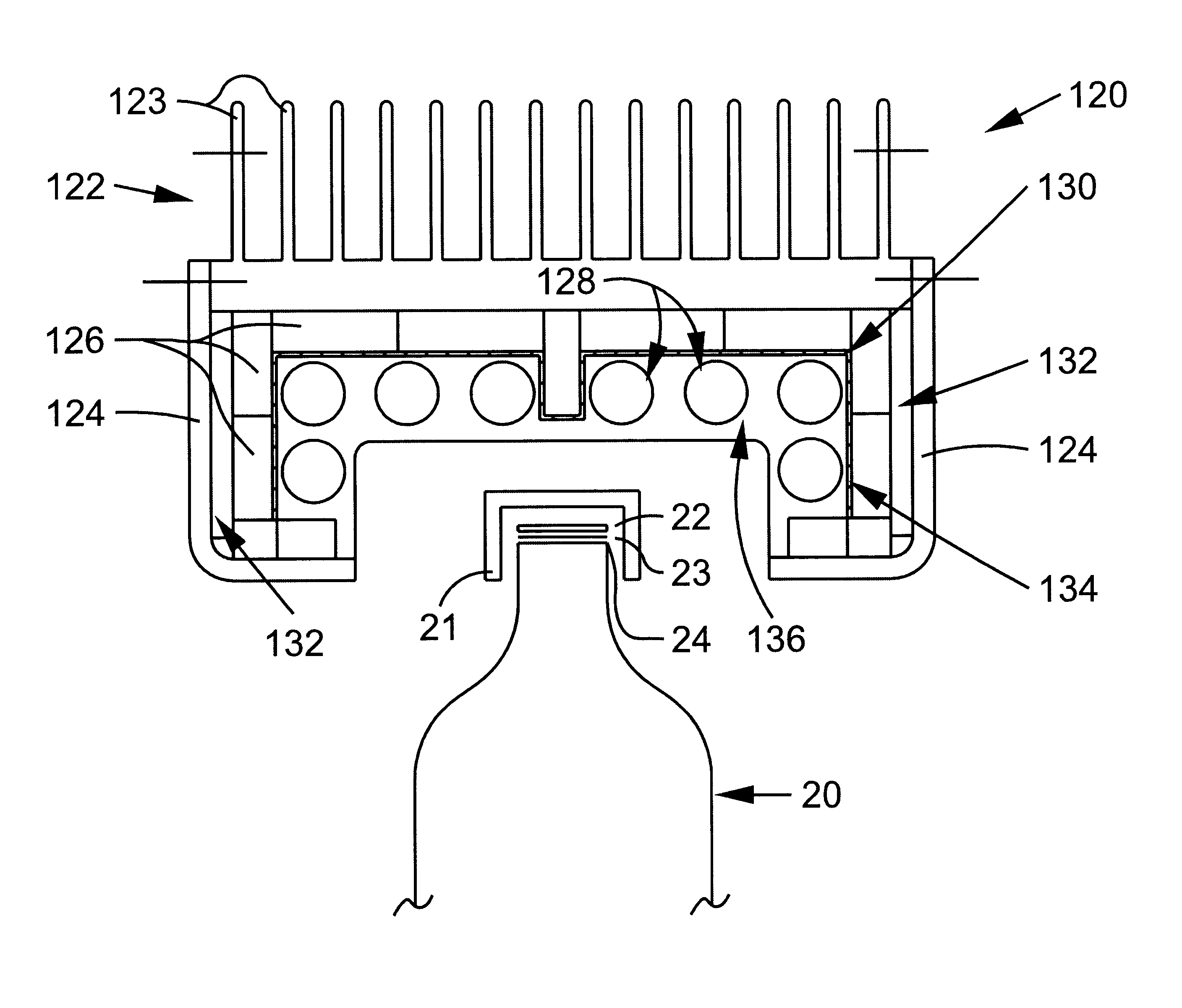
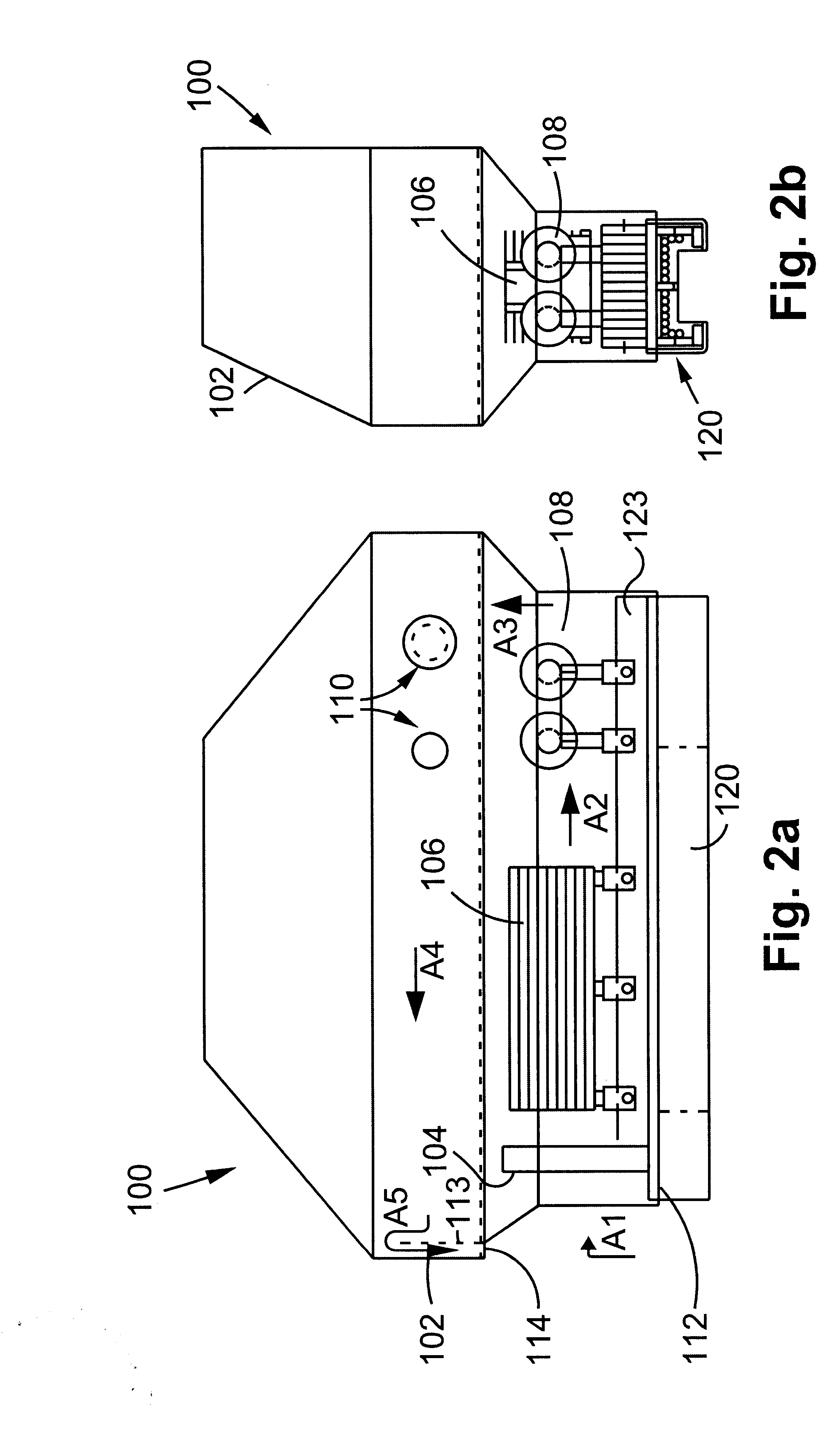
FIGS. 2a and 2b show front and side elevational views of the induction sealing unit 100, respectively. With reference to FIG. 2a, the induction sealing unit comprises a housing 102 and start and stop switches 110 disposed on the housing 102 for activating and deactivating the induction sealing unit 100. The components within the housing 102 ...


PUM

PropertyMeasurementUnit
poweraaaaaaaaaa
heat conductiveaaaaaaaaaa
electromagnetic fieldaaaaaaaaaa

Abstract

An induction sealing conveyor system includes an induction sealing unit coupled to an adjustment mechanism which adjustably positions the induction sealing unit with respect to a conveyor which moves a container to be sealed near a sealing head of the induction sealing unit. The sealing head includes ferrite cores and a litz wire coil formed on the ferrite cores which produces an electromagnetic field for hermetically sealing the container. The sealing head is entirely air cooled within the induction sealing unit.

Description

1. Field of the InventionThe present invention relates to an induction heating apparatus formed with slots on an interior portion thereof to assist with conduction of heat away from a central portion thereof.2. Related ArtInduction sealing units for hermetically sealing a container with a foil sheet are typically included in conveyor systems for high volume applications. These systems usually have a flat or tunnel sealing heads mounted above a conveyor which carries a plurality of containers to be sealed into proximity with the sealing head.The containers to be sealed are preconditioned to include a wax compound disposed between a foil sheet and the opening of the container. Usually, the foil sheet and wax compound are held in place by a screw-on or snap-on cap as is known in the art. Sometimes the wax compound is omitted and the foil sheet rests against a plastic material which forms the lip of the container.Once the preconditioned container is brought within a predetermined distan...

Claims


Application Information

Patent Timeline
Patent Type & Authority Patents(United States)
IPC IPC(8): B29C65/02B65B7/28B65B51/22H05B6/14B65B7/16B65B57/04B65G43/08H05B6/02
CPCB29C65/3656B29C66/836B29C66/72321B65B7/168B65B7/2878B65B51/227B65B57/04B65G43/08B29C65/3644B29C66/542B29C66/545B29C66/53421B29L2031/7158B29C65/3668Y10S53/02B29C65/368B29C66/81811B29C66/81871B29C66/8122B29C66/112B29C66/114B29K2827/18
Inventor SARLES, FREDERICK WILLIAMSJOHNSON, DOUGLAS A.
Owner AUTO KAPS
Why Eureka
Try Eureka